Home

Pool Bank Shot Practicing Tools

Leave a comment

BACKGROUND:  NOW or LATER either way

A summary of pool (Cue games) rules, equipment, lingo, … can be found here:

Much of the physics and math involved in making a bank (reflection) shot is summarized here:

Additional information for improving your understanding and skill can be found here:

For more than you want to know, but glad to know it exists; check this out:

For those with a physics interest there is a nice tutorial here:

LIMITATIONS:  WAIT a minute

The tools presented here are inaccurate!  To be used only in obtaining an approximate direction to send the cue ball.  The real skill in adjusting the shot direction involves making changes appropriate to the table conditions, the following assumptions and uncertainties.  Practice.

The important assumptions are that the angle of approach (incidence angle) is equal to the angle of departure (reflection angle); and that the ball has no spin.  Neither of these assumptions is valid!  (These conditions exist for light reflecting from a perfect mirror.)  The angle of departure will always be slightly less than the angle of approach because the table cushions absorb some energy.  Striking the cue ball exactly through the center of gravity and level, is extremely difficult to accomplish.  Variations from the ideal will results in a spinning cue ball, which will alter the bounce.

Another obvious assumption is that there are no obstacles (other balls or pockets) already in the chosen path.

TOOL 1:  MIRROR-MIRROR-MIRROR – set me Straight

Using mirror reflections, as an aid for determining, a 1st approximation for, a pool bank shot.

Much of the physics of using reflections is discussed here:

For a 3 cushion bank shot; 3 mirrors are used, one at each reflection (bank) position.

On the miniature table; place the BLUE/GREEN ball at the target location, place the WHITE cue ball (with attached cue stick and archery sighting) at the start location, point the cue stick (attached to the cue ball assembly) in a direction close to the final shot direction.  Make final adjustments by changing the pointing angle while sighting through the archery sight.  When the BLUE/GREEN ball image is contained in the sight circle, the correct shot direction is determined.  Trim your adjustments.   Note: sometimes the BLUE/GREEN ball will be hiding behind the cue ball assembly, use your judgement. 

The basic table setup for a 3 rail shot

Using 3 perpendicular Mirrors

This is the direction to shoot a 3 rail shot

to hit the target ball —->

Similar techniques are used for 2-rail and 1-rail bank shots where one or two mirrors are used.

TOOL 2:  JUST GO STRAIGHT THERE – bumps are Bounces

Using folded overladed transparencies that represent a REAL pool table, and several VIRTUAL pool tables as an aid for determining, a 1st approximation for, a pool bank shot.

I can’t find a reference for this overlay technique … but it works.

You start with a representation of a REAL pool table.  Next to it you place a number of VIRTUAL  pool tables.  The virtual table is the same size as the real table and is placed aligned and abutting the real table.  These virtual tables are attached to the real table with hinging material (scotch tape or real hinges) so that complete (flat) folding is possible.  Multiple virtual tables may be attached to previous virtual tables.  On the real table you mark the location of the cue and target balls.  You then draw a straight line from the cue ball location to a virtual table target ball location (not always easy to determine).  Draw with a marker pen that can be easily erased.  Each time the straight line crosses a table intersection it represents a rail bounce.  After a rail bounce encounter the line continues straight into another virtual table.  Now fold the tables so that they perfectly align. Observe the path of the cue ball when sent in the direction of the line (cue stick).

TOOL 3:  GROUP EFFORT With Big Mirrors

Probably the best tool is a set of 3 mirrors and 3 friends.  The friends hold the mirrors at the location of rail encounters.  The mirrors must be held vertically along the rail.  The cue stick is pointed at the reflection of the target and the cue ball is struck in that direction.  (Be sure to get the mirrors out of the way first.)  Friends can be replaced by C-clamps.

This is the basic table setup for a 1 rail shot

This is the pointing for a 1 rail to target

.

.

.

.

.

to hit the Target Ball ———–>

A Solar System Gravity Map

Leave a comment

I was impressed when ‘SpoonUnit’ (of thingiverse) presented the planets along a dimension other than the distance from the sun (using diameter instead).  I wondered if other dimensions might show the planets from interesting perspectives.  The dimension of mass and its resulting influence upon us, by way of gravity, seems promising.  Gravity has more influence upon us than many other metrics.

The source of the gravity information is:

https://en.wikipedia.org/wiki/List_of_gravitationally_rounded_objects_of_the_Solar_System

https://en.wikipedia.org/wiki/Gravity

I approximated and represent it all in a unique 3 dimensional map, using TinkerCad … 

https://www.tinkercad.com

The numbers represent the relative gravity – referenced to Earth, of gravity 1.

I 3d printed it … and made it ready for Thingiverse.

https://www.thingiverse.com

It can be viewed as ‘looking down a well’ at a clockwise spiral of equally sized objects.

Looking for the home feeling?” – go to Neptune (1.1), Saturn (1.1), Venus (.9) or Uranus (.9)

For the gravity that fits your muscles.

Looking for a familiar and easy life?” – go to Mars (.4), Mercury (.4), Io (.2) or Luna (.2)

For existence that we have some experience with, and that requires little effort.

See Jupiter as the major mover.

https://en.wikipedia.org/wiki/Gravity_assist

The other solar system object approximate zero-g environments – that we have experience with.

https://en.wikipedia.org/wiki/Weightlessness

Ponder the 5 planets of near equal mass – this may be a clue to something.

Remember how important, for chemistry, the electron grouping was …

1 5 2 2 3 is that like the electron energy levels of 2 6 10 14 18 ( s p d f g)?

https://en.wikipedia.org/wiki/Electron_shell

Aside: note that s = 2, p-s = 4, p+s = 8, p+d = 16 (also f+s), f+d+p+s = 32, …

looks like a binary influence may be at work here … ?

The grouping could also be 1 2 3 2 2 3 … or …

Happy pondering!

Numbers for Geometry

Leave a comment

My solution to a nagging problem in Mathematics

I became intrigued by the variety of ways to establish a coordinate system for representing solid geometry in numeric terms.

https://en.wikipedia.org/wiki/Cartesian_coordinate_system

I remember, as a young person, being amazed at the difficulty of transitioning from plane to solid geometry.  Being comfortable with x-y graphs, I felt that it would be easy to add a z axis and be done with it.  I soon found that confusion prevailed.  Teachers at the blackboard oriented the axes so that y was up and z came out into the room.  My intuitive choice was to have z going up out of the paper at my desk.  I found agreement with my system when describing ‘ground vehicles’, where x is to the front and z is up.  But when working with aircraft I found that x was the same as for ground vehicles but that z pointed down.  And for water vehicles, where z is meaningless (except for submarines), the aircraft convention was adopted.  Space is a different story all together, where up is not defined.

https://en.wikipedia.org/wiki/Aircraft_principal_axes

https://en.wikipedia.org/wiki/Axes_conventions

Mathematics does not settle the confusion, when it accepts any orientation as equivalent, as long as the ‘right hand rule’ convention is followed.

https://en.wikipedia.org/wiki/Right-hand_rule

Most people could care less.  With the introduction of 3d printers and design tools readily available, more people are confused.  Which way is ‘up’?  One of my favorite books from childhood was ‘Flatland’ by Edwin Abbott where a character struggled with the suggestion of ‘up without north’ and concluded that the concept was silly.

https://en.wikipedia.org/wiki/Flatland

I have concluded that this confusion is silly in a system so important, for describing the world we live in.  The solution I chose was to relate the axes to the only meaningful perspective – the individual’s senses.  The x axis points in the direction of visual interest and mobility preference.  X points ahead to the front.  Z is another intuitive sense and must be pointing up.  This requires that Y must be pointing to the Left; to follow the right hand rule and the mathematical definition of orthogonal axes.  We are after all, a ground vehicle.

So to aid in remembering this system, and it’s associated conventions for roll, pitch and yaw; I  have created a structure using my hero Albert Einstein as the model. 

https://en.wikipedia.org/wiki/Albert_Einstein

The x-axis comes out of his head in the region of the eyes, providing for the ROLLing of eyes.

The z-axis comes out of the top of his head, providing for the YAWing of disagreement.  And the y-axis comes out of the left side of his head, providing for the PITCHing of agreement.

I decided to further enhance my Albert Einstein model by allowing us to view into his thoughts; by not completing the construction of the top of his head.  Looking into his head we get a glimpse of his thought processes. We find 4 major areas of concentrated innovations.

Area 1 relates to the ‘Photoelectric Effect’ and is represented by a matrix of similar objects.

I’ll leave it to you, to relate Quantum to the observed impact of light dislodging an electron only if the frequency is appropriate.  He showed that the intensity and duration of the light had no effect upon releasing electrons; only the frequency.  Concluding from that an idea of discrete levels and units.  And that light can influence matter.

https://en.wikipedia.org/wiki/Photoelectric_effect

Area 2 relates to ‘Browning Motion’ and is represented by a rotated normal distribution curve, compared to the Apollo spaceship.  I’ll leave it to you, to relate Statistics to the observed motion of a pollen seed being moved randomly about by impacts with water molecules.

https://en.wikipedia.org/wiki/Brownian_motion

Area 3 relates to the relationship between Time and Space and is represented by the light cones of past and future interacting with the present space plane.  I’ll leave it to you, how the ‘special theory of relativity’ can unify time and space.

https://en.wikipedia.org/wiki/Special_relativity

Area 4 relates to the relationship between Mass and Energy and is represented by the famous equation that almost everyone knows.  I’ll leave it to you, to ponder the enormous amount of energy released by the conversion of even a tiny amount of mass.  Take one of the largest numbers you can think of, the speed of light (very fast), multiply it by itself, then multiply that by the mass converted and you get a really humungous number for the energy released.  So much so, that over many decades of failed attempts to contain it, we still struggle with controlling it.

https://en.wikipedia.org/wiki/Mass–energy_equivalence

My completed model includes an idea of the frustration of living in the shadow of greatness.  We see a smaller pale imitation of the colorful Einstein model standing off to the side, admiring with awe the accomplishments of a hero. 

Yet we know that the effort to assign numbers to physical objects will continue to broaden our understanding and appreciation of nature.

Click on the image to the right for a video of my model.

Compliant Material

Leave a comment

Justification for buying a 3D printer …

or How much I enjoy Making Compliant Materials with my Snapmaker 3D printer+

I am excited about this field of Mechanical Engineering and the Computer Aided Design and Manufacturing currently available to the public.  Working with compliant material is much easier than manufacturing using non-compliant metal.  The 3D printer technology is a perfect companion for this material. 

This post is a collection of links and descriptions of compliant mechanisms, many of which I printed on my Snapmaker 3D printer.

The following information MUST be somewhat understood before the wonder and beauty of this material can be fully appreciated.  The lecture series is optional but is very informative and well presented.  Be careful, the advertisements can be enticing.  This is just a sample of the instructional material available to you.

Visit to BYU lab … Derek Muller and Larry Howell Video

Definition:

https://en.wikipedia.org/wiki/Compliant_mechanism

Derek Muller Video

https://www.veritasium.com/videos/2021/2/18/why-robots-that-bend-are-better

Derek Muller Video

https://www.veritasium.com/videos/2019/10/4/engineering-with-origami

Larry Howell Video

https://www.compliantmechanisms.byu.edu

https://www.compliantmechanisms.byu.edu/maker-resources

Robert J Lang Video

https://langorigami.com

Lecture Series … Jonathan Hopkins

FACTS of Mechanical Engineering Lecture Series … Jonathan Hopkins

https://www.youtube.com/channel/UC5Jz6SBlu2Sv61kfssv4DOw

Cool Prints

“Hide Box” Magic Illusion

1 Comment

Snapmaker, the people who made my 3D printer/Laser cutter & engraver/CNC carving machine, is conducting a contest for creations using the machine.  I have trouble passing up a contest, especially since I’ve created so many masterpieces.  And the prize is a machine add-on to enable etching on a round surface drinking glass. 

They encouraged submissions that employed recycled material; a natural for my obsession with reusing wooden cigar boxes.  

I have been thinking of creating models of magic stage illusions.  At the top of the list was what is called a “production box”, a box that appears to be empty when examined through the “front” door, but which contains hidden items (like rabbits, women, lions, elephants, …) obtained through the “top” door.  The illusion of emptiness is created using a mirror and judiciously placed objects surrounded by wall and floor coverings using symmetry.  The modern mind, conditioned heavily by vertical and horizontal architectural environments, is easily confused by such images.

So I collected the parts and designed a very effective illusion.  I started with my cigar box collection for the physical sides, top and bottom of my “hide box”.  I paid dearly (about $50) for a quality front surface reflective acrylic mirror.  Obtained a box design from ‘MakerCase’ and used Tinkercad and Inkscape to embellish it.


The Hide Box from the outside back
The Hide Box from the outside showing the 2 doors
Hide Box with doors open

The “floor covering” is a favorite M.C. Escher drawing.  You may be intrigued to ponder that this drawing was made on Christmas 1941.  Considering what was going on politically in his part of the world, we can imagine his thoughts.  This drawing very effectively creates the “back” wall, which is really the floor.

Hide Box with front door open

I believe that the use of horizontal symmetry of selected letters (B C D E H I K O X) to add to the overall illusion is original.  I used the words “HIDE BOX” to accomplish this.  I would have liked to use “OKEECHOBEE OHIO” but couldn’t fix it in.  I also considered using letters with vertical symmetry (A H I M O T U V W X) like MATH and TOY but decided to save those for another project.

The side walls are covered with beautiful Islamic tiling, perfect for the angular symmetry needed.  These tiles I found in Pedralbes Royal Palace, Barcelona Spain.

The ball and small green box are simple additions to further confuse a befuddled mind.

The hidden item I have chosen is a famous world leader, which you may remember, who appears to be very upset with himself.

Hide Box with top door open

Here is a video which will help explain everything …

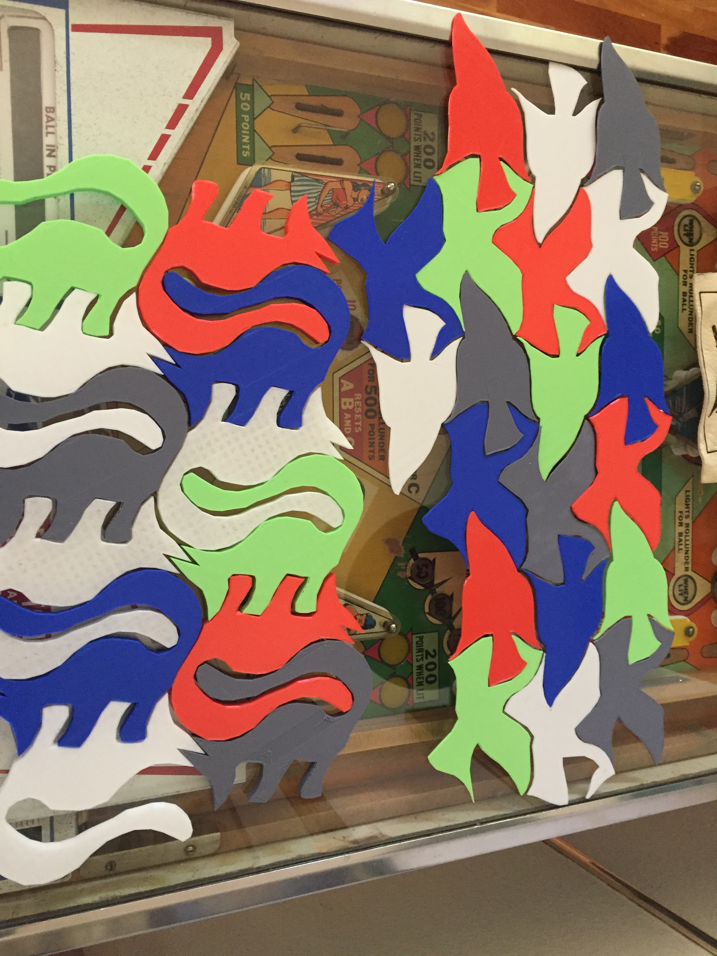
M.C. Escher puzzle tiles

Leave a comment

Making 3D Silhouettes from Pictures:

CookBook Instructions

The sequence that I follow is:  1st (*) I make a JPEG image of a picture containing the object to be 3d printed.  Next (**) I select the object to be 3d printed and save it in SVG format.  Then (***) convert the SVG to STL, and finally (****) slice the STL into G-Code ( the 3d printer compatible format).  

(*) Sources of JPEG Images:

Your Camera/Phone; you can capture essentially anything the eye can see.

Your Computer Screen; using “Screen Dump” (Command+Shift+3 on Apple)

(NOTE: What you have just done or about to do may be illegal!)

Copyright and Patent Rights may exist – don’t think of selling anything!

for example:

International Copyright laws protect all of the work of M.C. Escher, as well as his spoken and written words. Any reproduction of his work, including downloading, is prohibited without the express written permission The M.C. Escher Company.

(**) Image Editing, Translating, Manipulating, Altering, Enhancing, Value Adding, Fair Using, Transforming:

(NOTE: What you think you are doing is legally important!)

I use “Inkscape” to select the object to be 3d printed, and save in SVG format.  Inkscape offers several ways to create a selection path around a portion of the image.  I use the Bezier Curve tool.

Inkscape offers a SVG format Save option, but not the STL format that is needed.  

(***) “TinkerCad” can be used to translate SVG format to STL format.  

(****) There are a number of Freeware Slicing tools. Most 3D printers come with their own.  My printer (SnapMaker) comes with a slicing tool, which I use.  It also handles the printing details like scaling and quality control.

I then use a memory stick to move the G-Code format file from the computer to the 3D printer.

The Sequence is:  Image -> JPEG, -> SVG, -> STL, -> G-Code, -> 3D Printer.
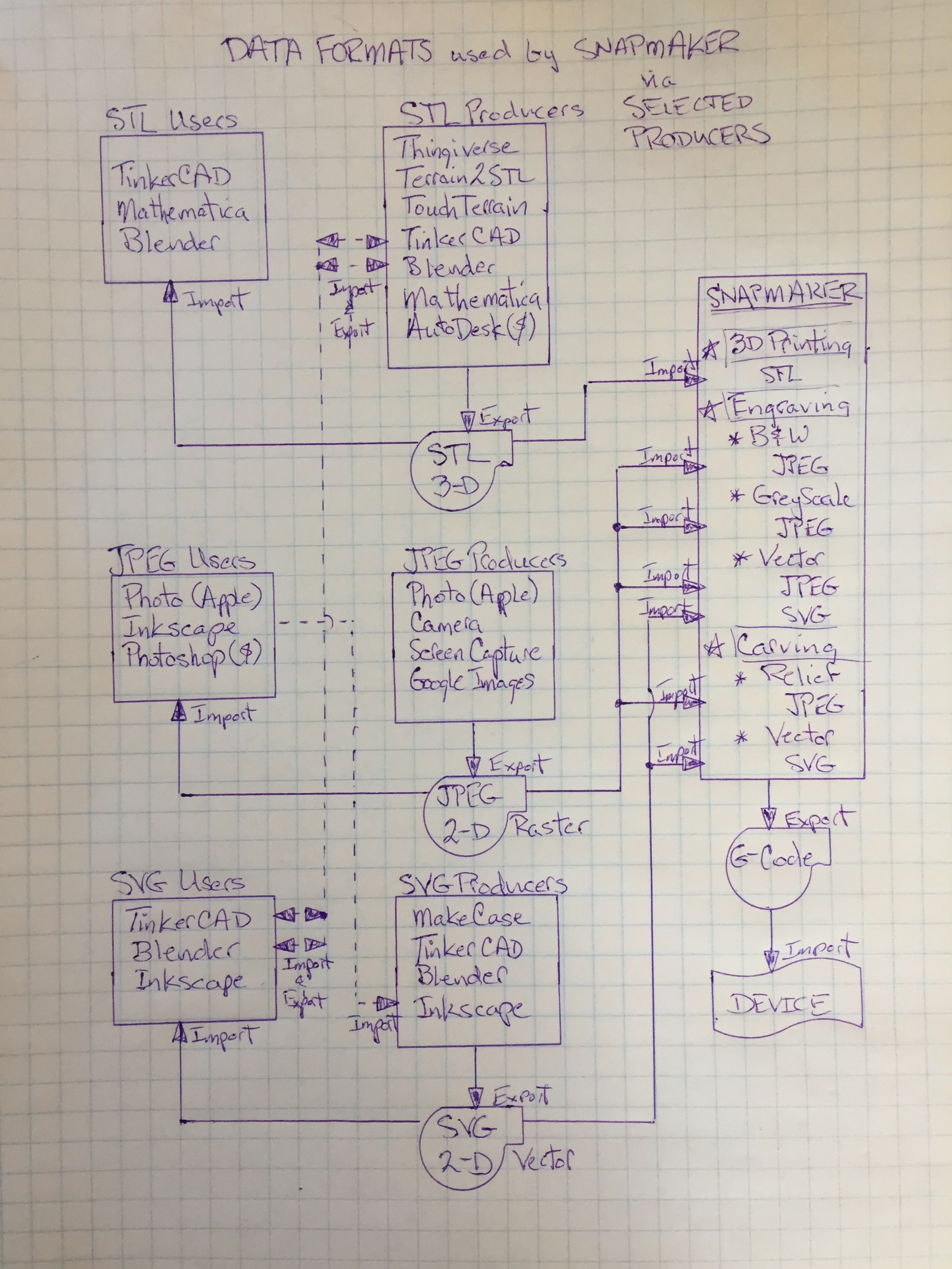
OR find

‘Ready made’ sources of STL files:

thingaverse.com is a shareware website where you can share your creations.

The creations that others will share are numerous and wonderful!

OR enjoy

Your own creations, using tools like:

TinkerCad

Mathematica

TouchTerrain

Terrain2STL

Inkscape

Blender

Boolean Algebra & Multiple Negatives

Leave a comment

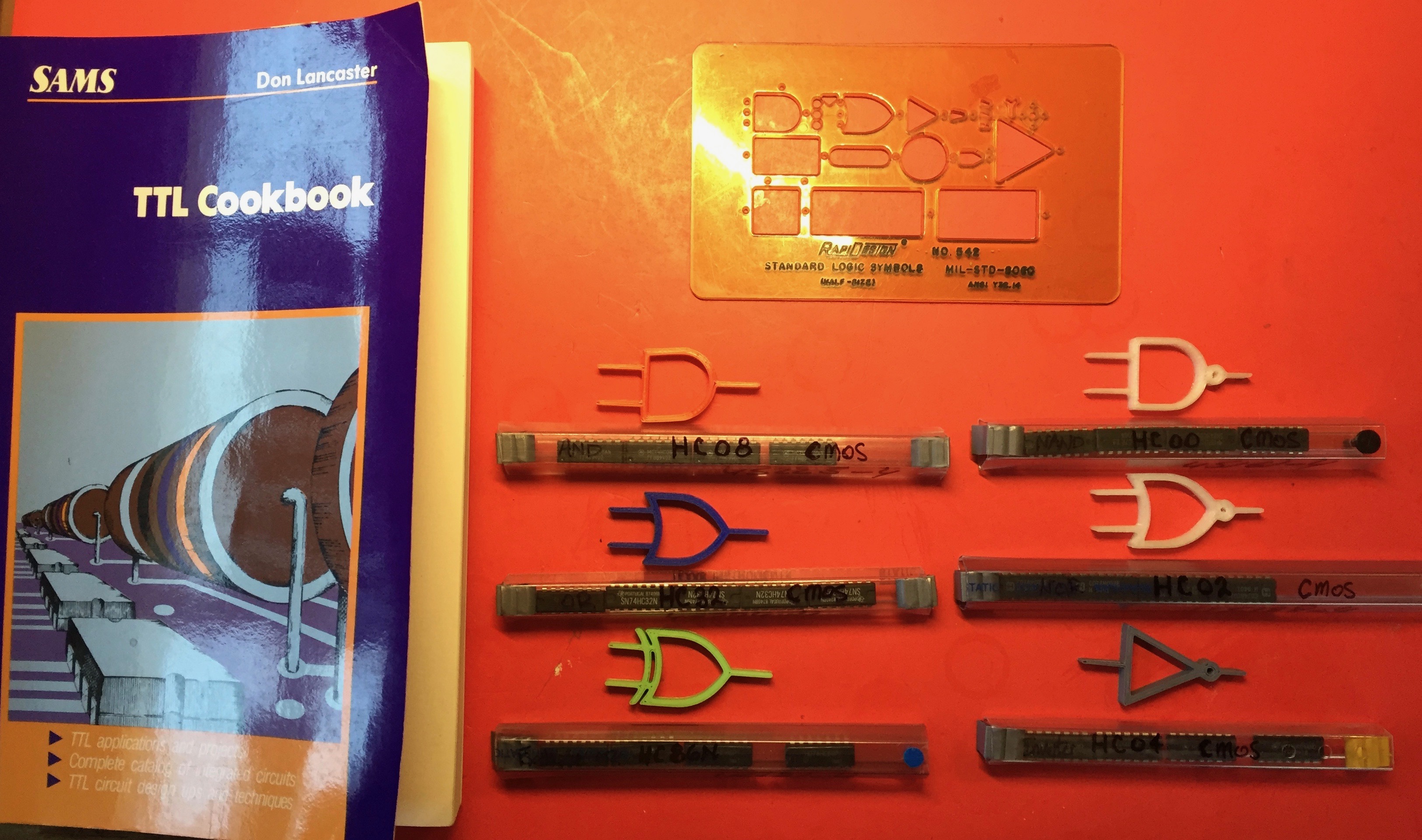
Tools of the Trade:  Engineering design Items contained in the following image are …

The “TTL Cookbook”, published in 1974, became the standard reference to TTL (transistor-transistor-logic) devices.

A “Drawing Template”, of standard logic symbols, used for schematic drawing of logic designs.

“Protection Tubes”, containing the standard packaging (chips) of integrated circuits.  Depending upon how you interconnect these logic blocks, you can build a computer, a calculator, an electronic music system, a digital voltmeter, a counter, a television terminal readout display, a color-tv dot-bar generator, educational demonstrators, or any of thousands of other possibilities.  While a single “yes-no” decision by itself usually is not too useful, the proper combination of grouped “yes-no” decisions taken together can represent a number, a word, a command, a musical note, a test signal, or practically anything else you might like.

LogicGates

Introduction to Boolean Logic:

The Khan Academy has several lessons providing an excellent introduction:

Logic Gates

Boolean Logic

Wikipedia provides very useful reference:

Boolean Algebra

And many Educational Institutions sources:

Princeton

WordPress

Medium

Computer Aided Design applications which are “Open Source” (Free and Modifiable):

TinkerCAD

Blender

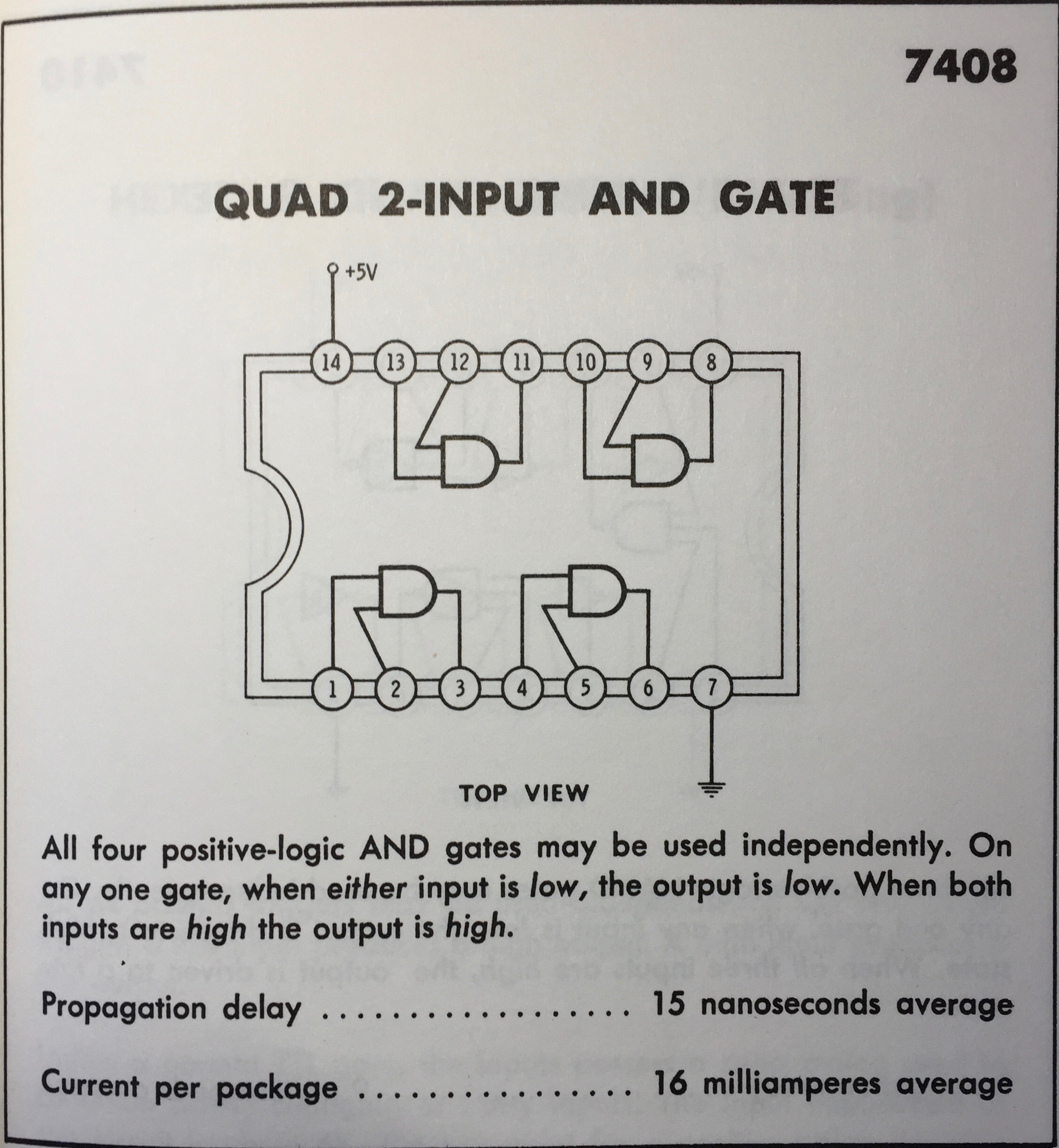
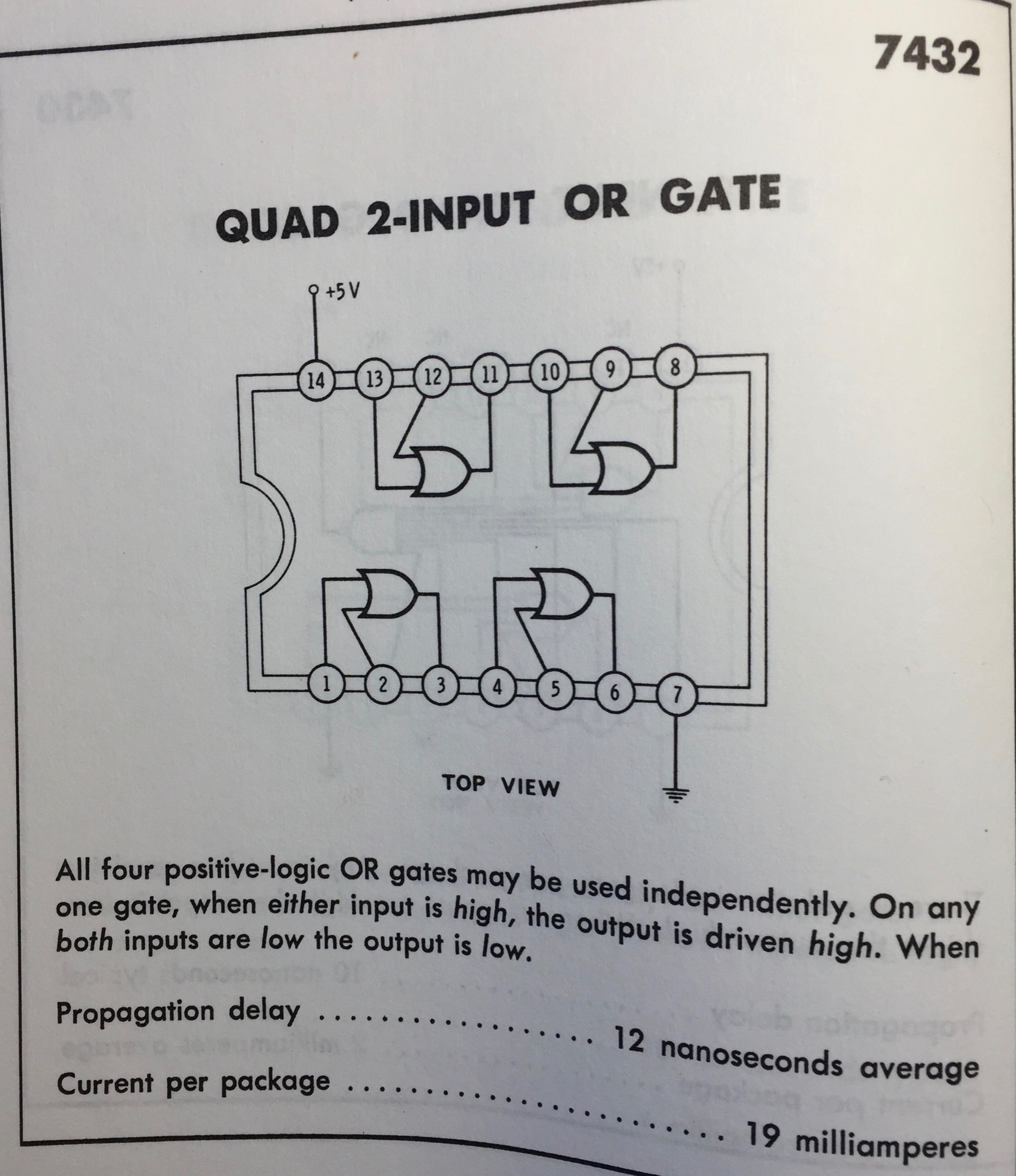
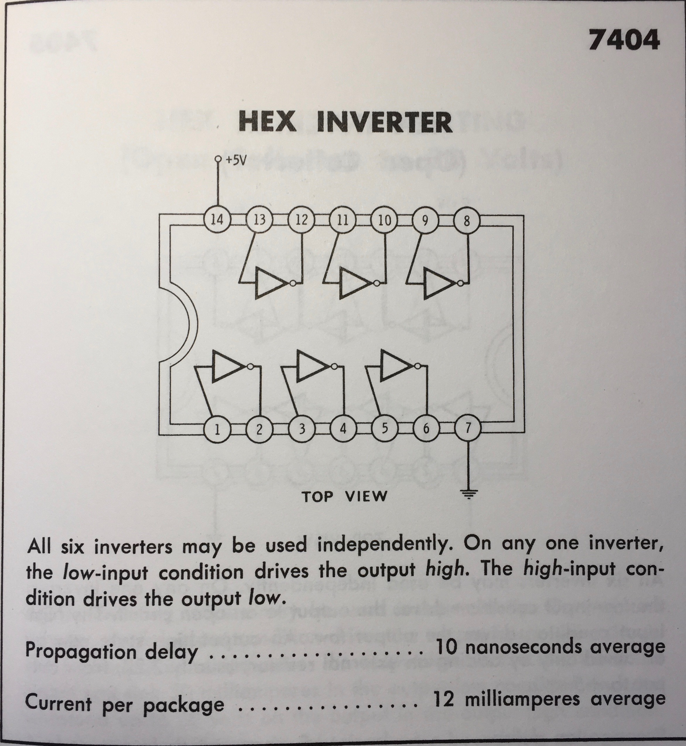
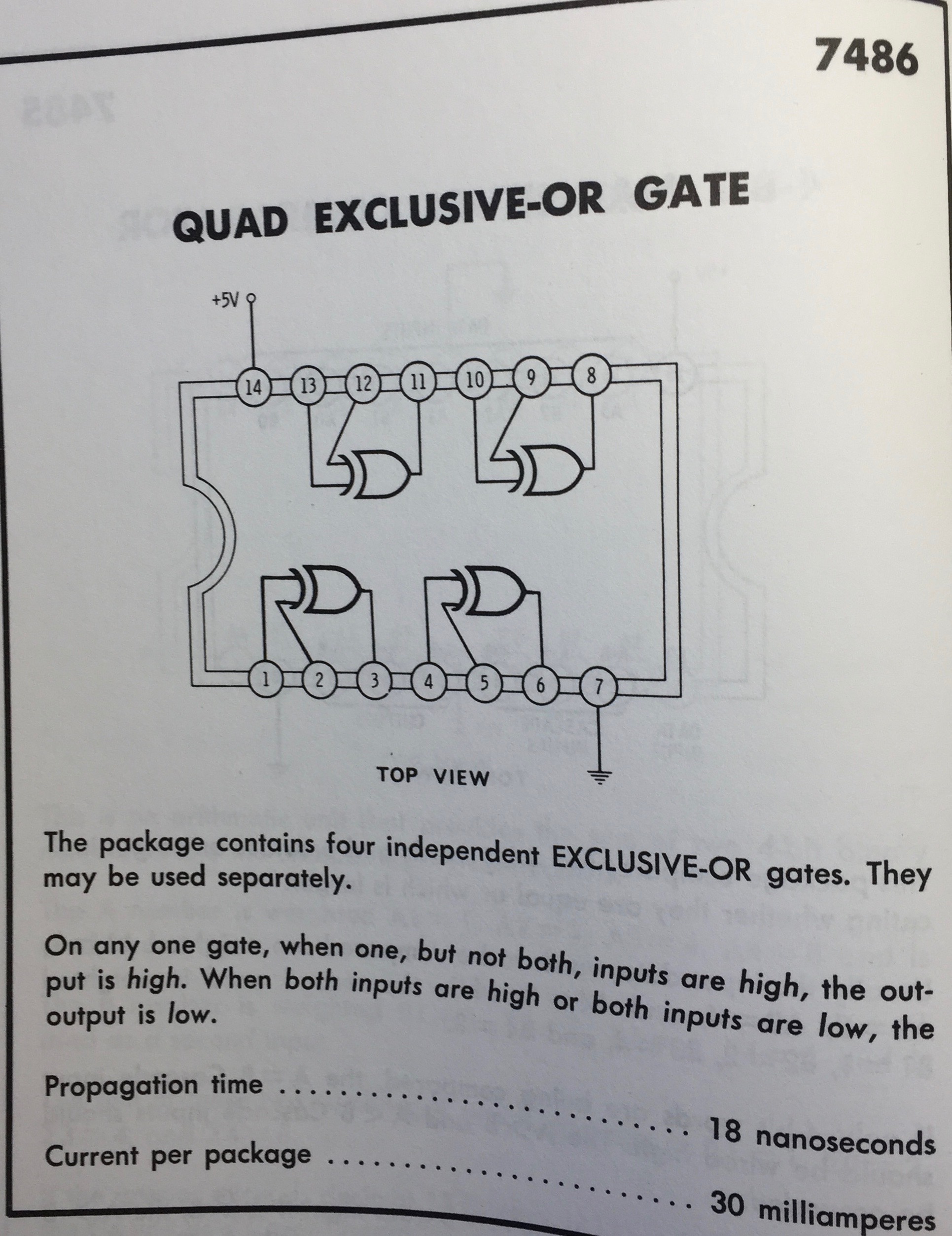
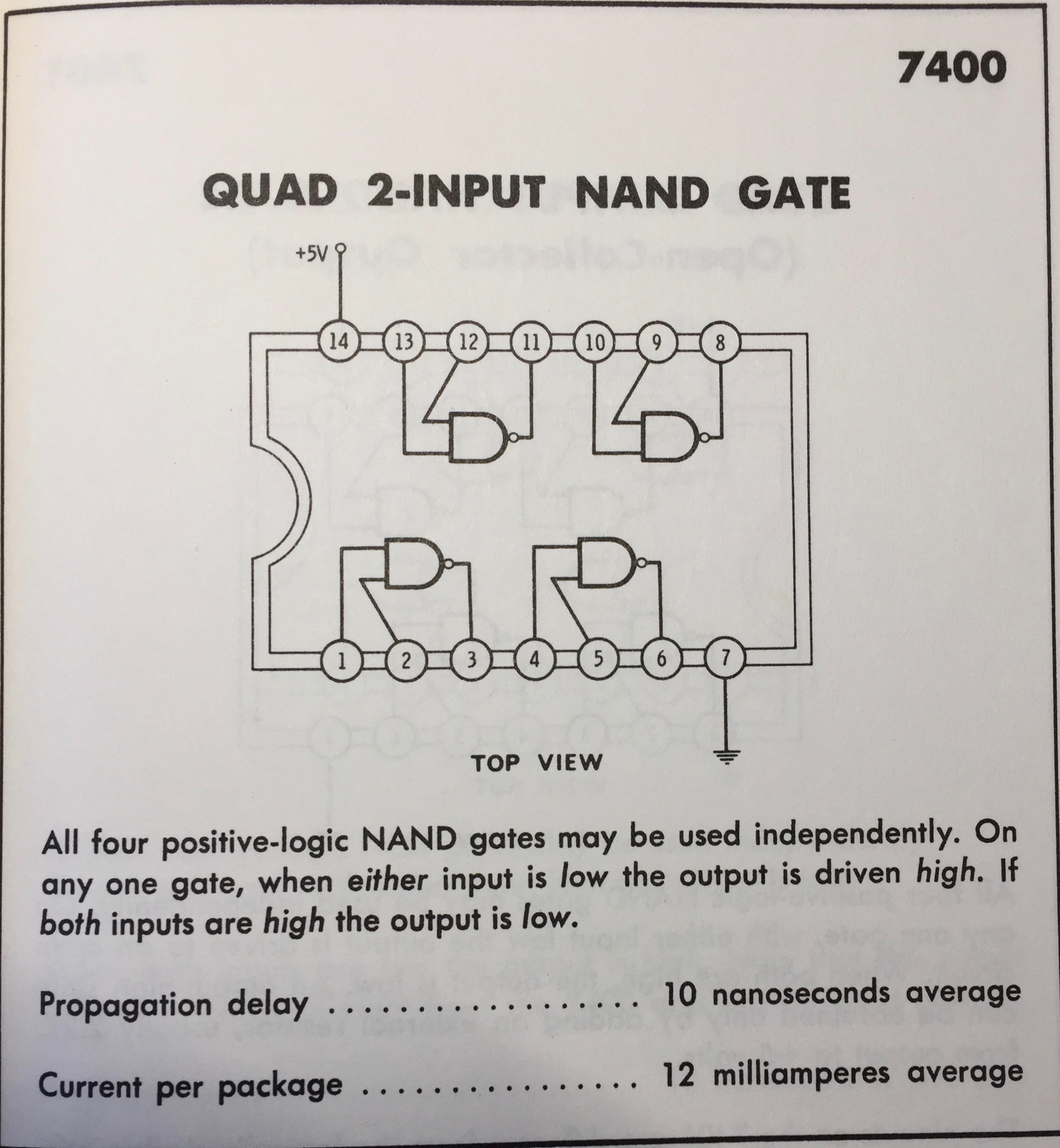
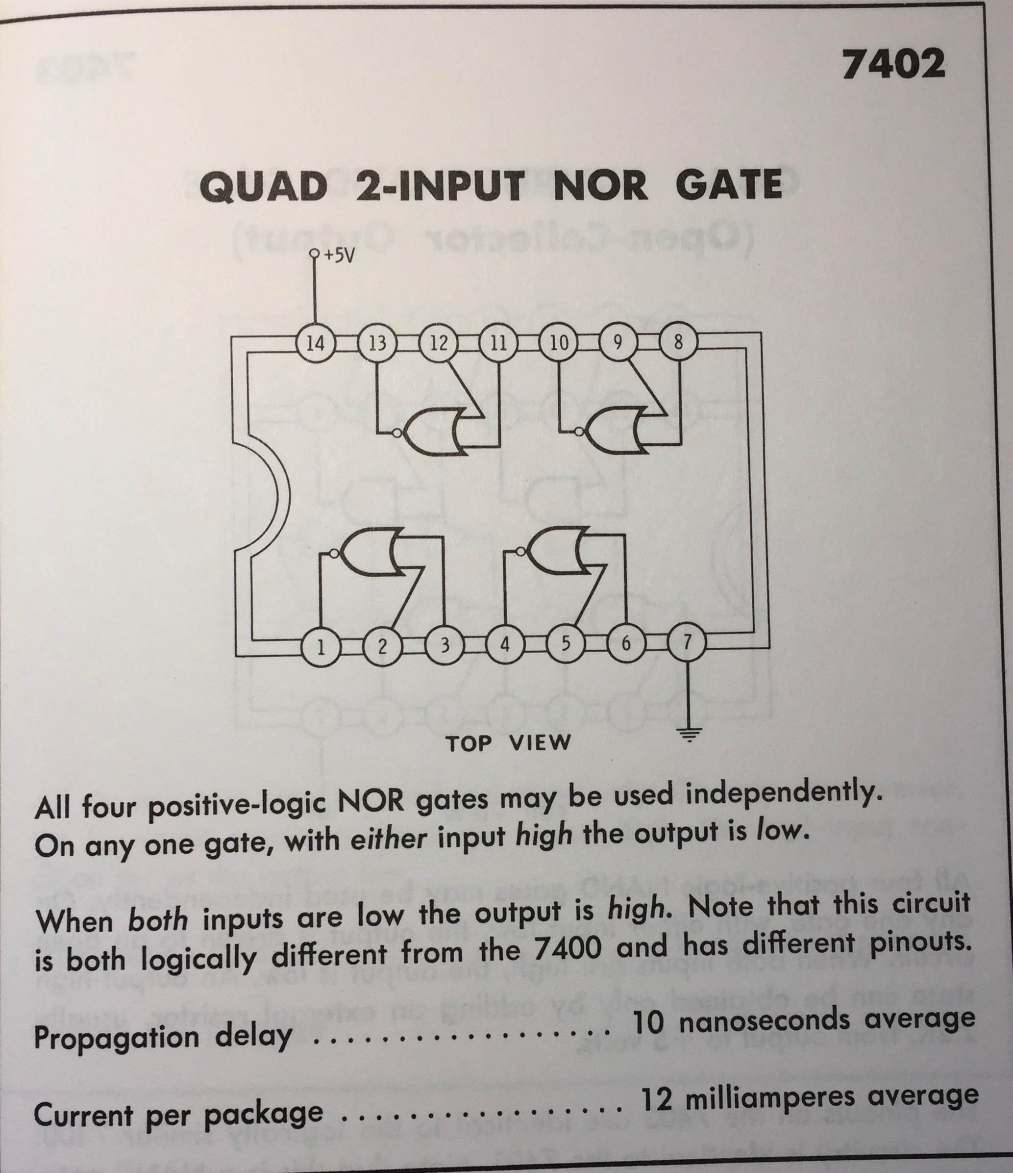
The following images are from the “TTL Cookbook” of selected TTL circuits.  Each covers essential information you might need to connect or intelligently use the integrated circuit.  The selected operations are those commonly found in Computer Aided Design (CAD) tools for creating solid objects. See: Constructive Solid Design for details.

The AND logical operation, producing what is referred to as an Intersection or a Conjunction and commonly represented by the ampersand symbol (&):

And

The OR logical operation, producing what is referred to as a Union or a Disjunction and commonly represented by the symbol (v):  

Or

The NOT logical operation, producing what is referred to as a Difference or a Negation or a Inverter and commonly represented by the symbol (- or \):

Inverter

The XOR logical operation, producing what is referred to as an Exclusive OR:

ExclusiveOr

The NAND logical operation, producing what is referred to as a Not AND:

NAnd

The NOR logical operation, producing what is referred to as a Not OR:

NOr

Boolean Logic use in Everyday activities:

How to get the truth from a chronic lier?  Ask them “What would you say, if I ask you …?”.

In some languages, double negatives cancel one another and produce an affirmative.  Languages without negative concord typically have negative polarity items.  Examples: ”ever”, “anything” and “anyone” in the sentence “I haven’t ever owed anything to anyone” (cf. “I haven’t never owed nothing to no one” in negative-concord dialects of English, and “Nunca devi nada a ninguém” in Portuguese, lit. “Never have I owed nothing to no one”, or “Non ho mai dovuto nulla a nessuno” in Italian). Note that negative polarity can be triggered not only by direct negatives such as “not” or “never”, but also by words such as “doubt” or “hardly” (“I doubt he has ever owed anything to anyone” or “He has hardly ever owed anything to anyone”). In English, double negatives can sometimes be used for affirmation (e.g. “I’m not feeling not good”), an understatement of the positive (“I’m feeling good”). There isn’t no other way.= There’s some other way. Negative: isn’t (is not), no vs.  There isn’t no other way!= There’s some other way!

“I don’t disagree” could mean “I certainly agree”, “I agree”, “I sort of agree”, “I don’t understand your point of view (POV)”, “I have no opinion”.

Whereas some double negatives may resolve to a positive, in some dialects others resolve to intensify the negative clause within a sentence. For example:

  • I didn’t go nowhere today.
  • I’m not hungry no more.
  • You don’t know nothing.
  • There was never no more laziness at work than before.

In contrast, some double negatives become positives:

  • I didn’t not go to the park today.
  • We can’t not go to sleep!

I don’t want to know no more

I’m not doing nothing; I’m thinking.

I did not go nowhere resolves to I went somewhere.

“If you don’t wanna go nowhere…”

“Badges? We ain’t got no badges. We don’t need no badges!.”

“I won’t not use no double negatives”

“I ain’t never heard of no licence.”

“Inside toilet? I ain’t never not heard of one of them nor I ain’t nor nothing.”

“We don’t need no education / We don’t need no thought control”

(I Can’t Get No) Satisfaction“)

Other languages, doubled negatives intensify the negation – negative concord or emphatic negation

Portuguese, Persian, French, Russian, Spanish, Neapolitan, Italian, Bulgarian, Czech, Polish, Afrikaans, Hebrew, Ukrainian, and some dialects of English, such as African-American Vernacular English, are examples of negative-concord languages

negative-concord languages are more common than those without.

And what about 2 Positives … can they make a Negative? ,,, ?

A English professor was giving a lecture on ‘Double Negatives’ in his class and said, “It is interesting that two negatives make a positive but there are no two positive words that can make a negative in the English language.”

‘Yeah, right.’ A student exclaimed from the back of the class.

Negatives

Puzzles:

Maker Tools

1 Comment

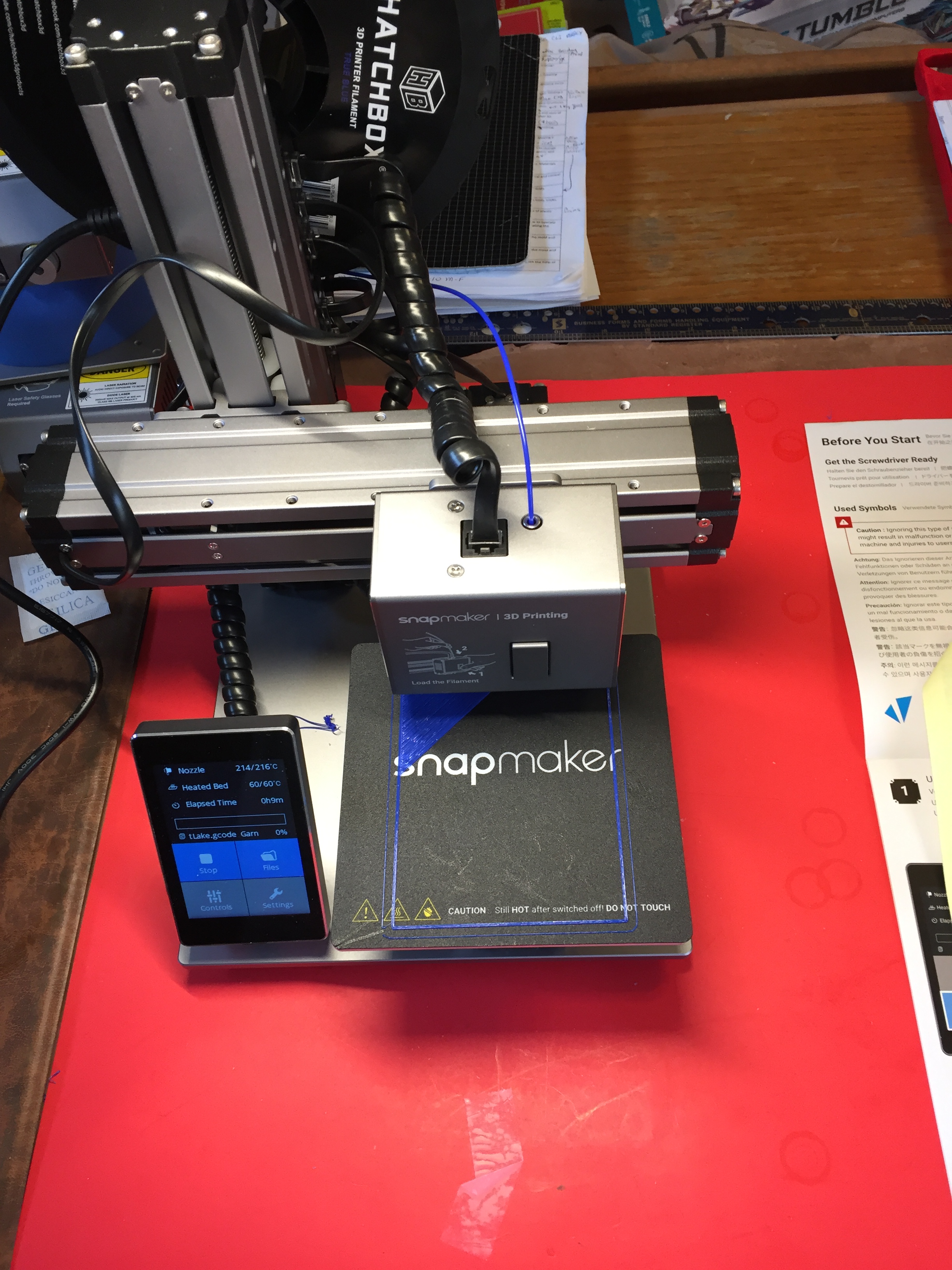
I recently attended a Rapid Prototyping class at our local Vocademy.  Merle, my wife, gave me the class for Hanukkah/Christmas.  The class introduced me to 3D printing, Laser Engraving, Laser Cutting, CNC machinery and much more.  I learned that “If you can’t open it, you don’t own it!”, among much more.  It was a wonderful experience which encouraged me to buy a 3 in 1 prototyping tool.  I bought the version 1 of SNAPMaker.

SnapMaker

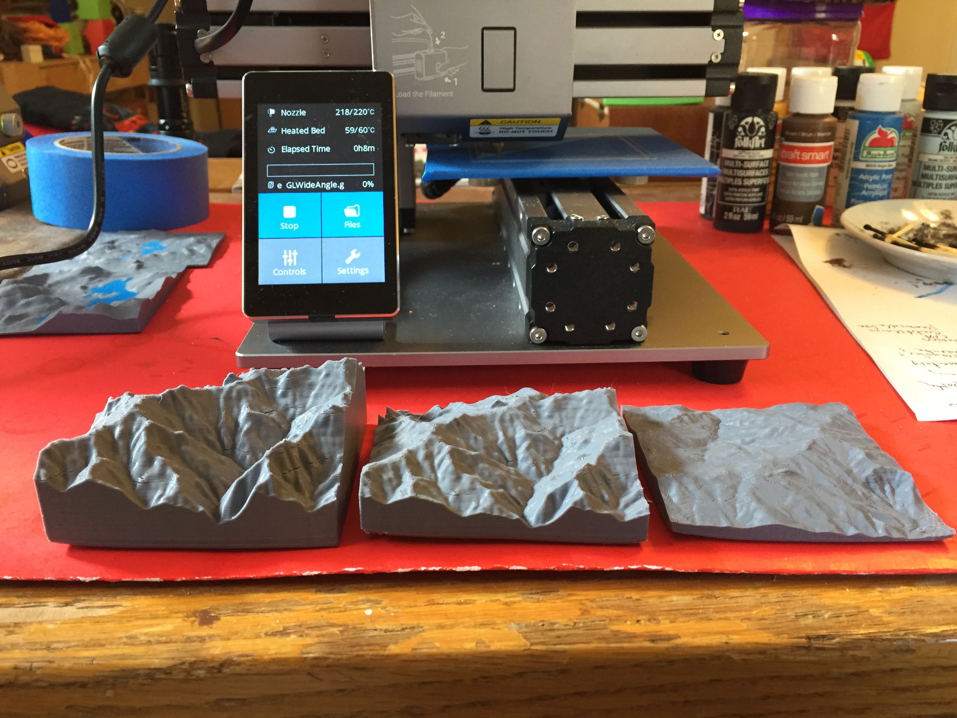
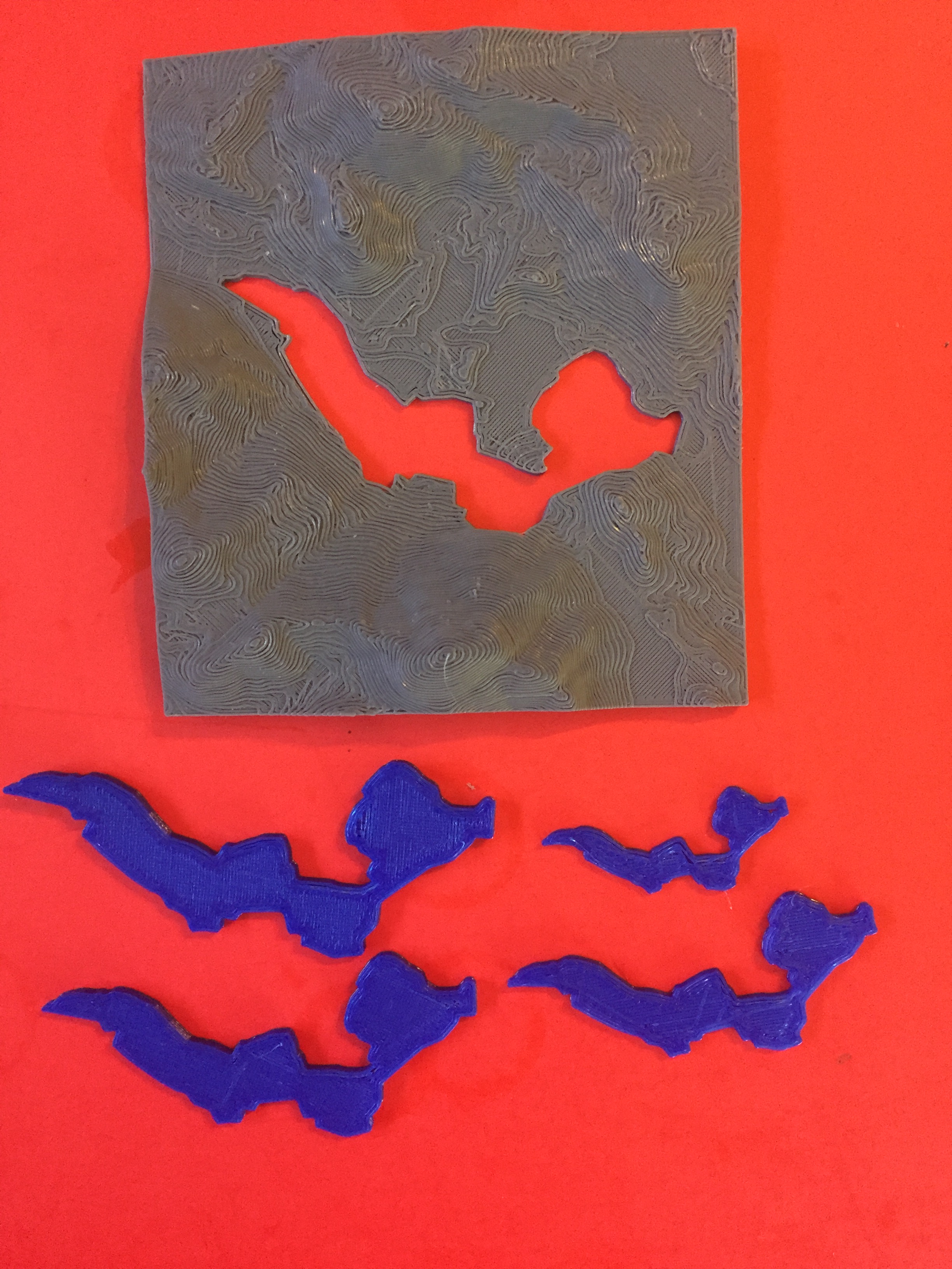
I have enjoyed exploring the 3D printer to make elevation maps of mountainous areas, using free web sites TouchTerrain and Terrain2STL.  Here are 3 that I did of my brother’s home area in Mendocino County California.  I used 3 different scalings of elevation to test psychological realism.  I liked the times 2 and times 3 exaggerations best (actually I settled on 1.628; the Golden Ratio):

BellSprings

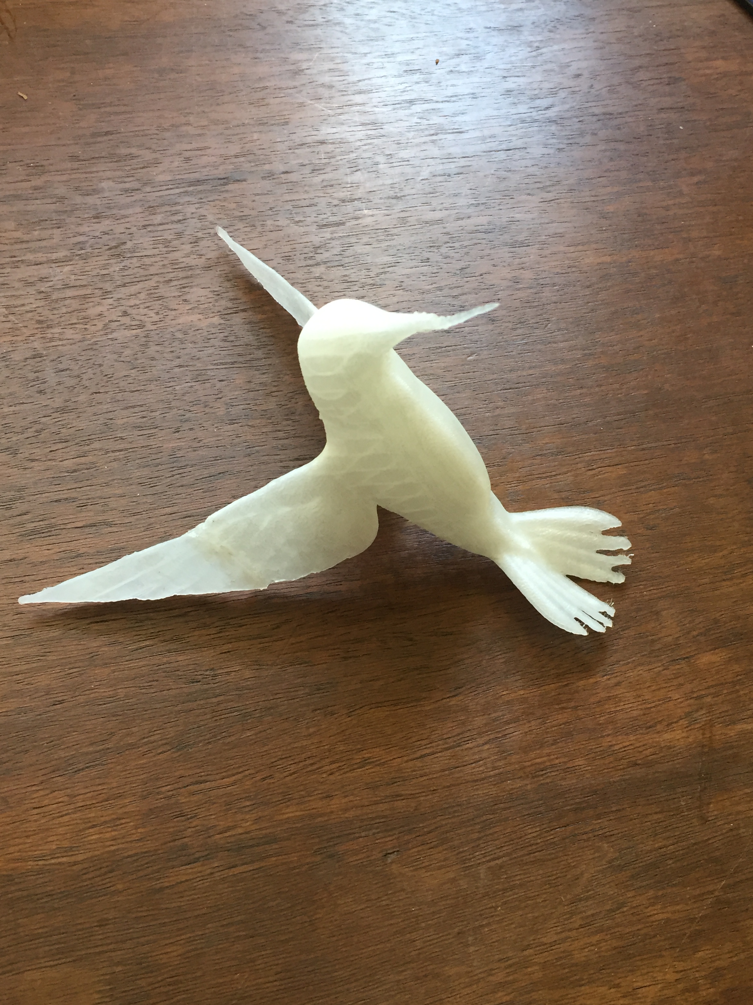
Other explorations include an artistic hummingbird (Broken Wing & Crooked Snout).  This was my first experience with 3D Printer Crutches:

HummingBird

And several Etchings, Engravings and a wonderful exotic gear arrangement:

Products

Here are the Cubic Gears in action:


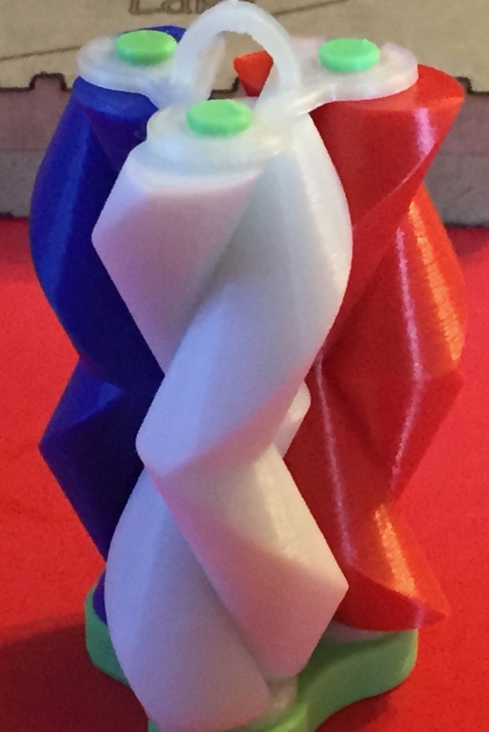
Here is a wonderful Spiral Gear arrangement from Thingiverse (a source of Open Designs)

SpiralGears

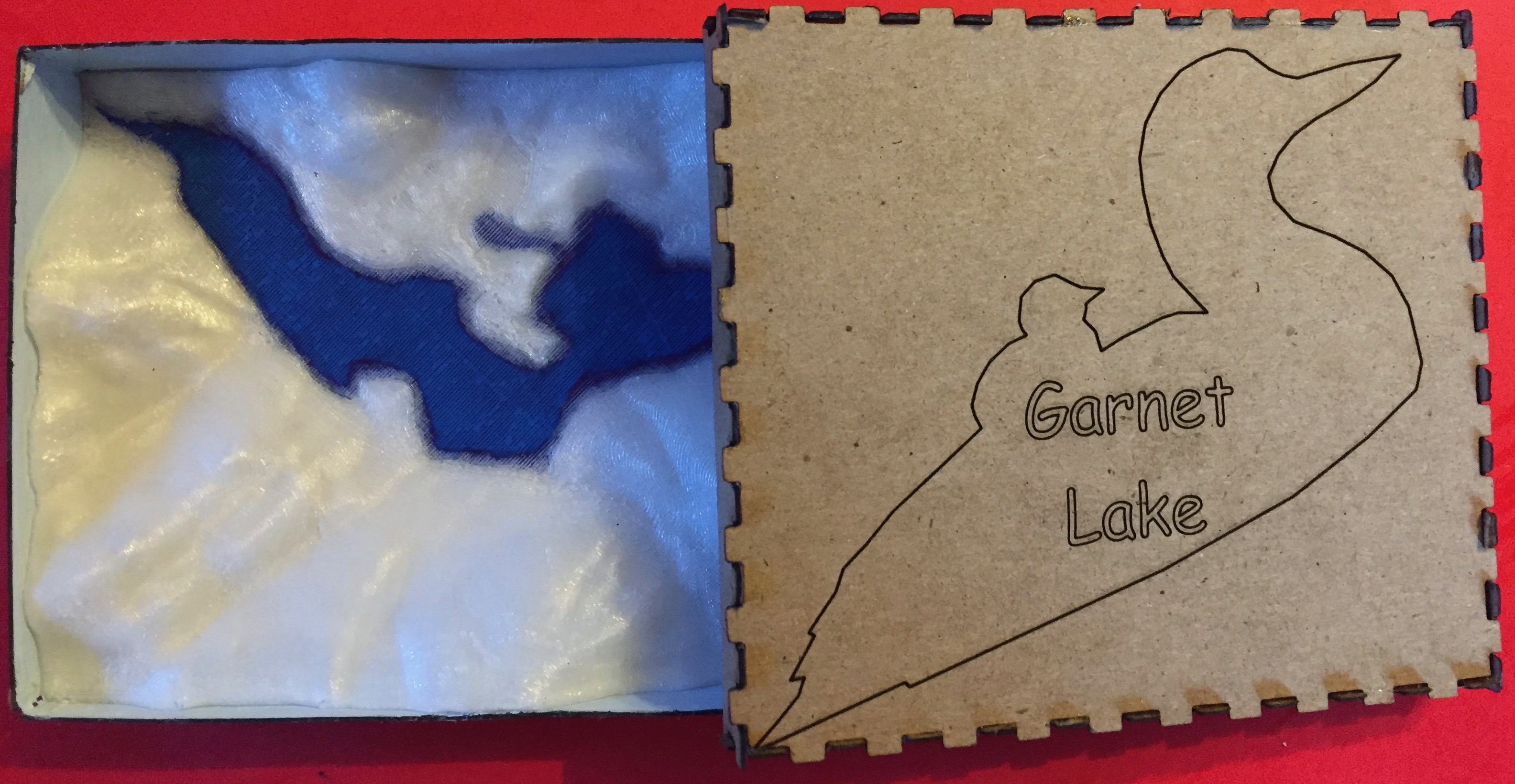
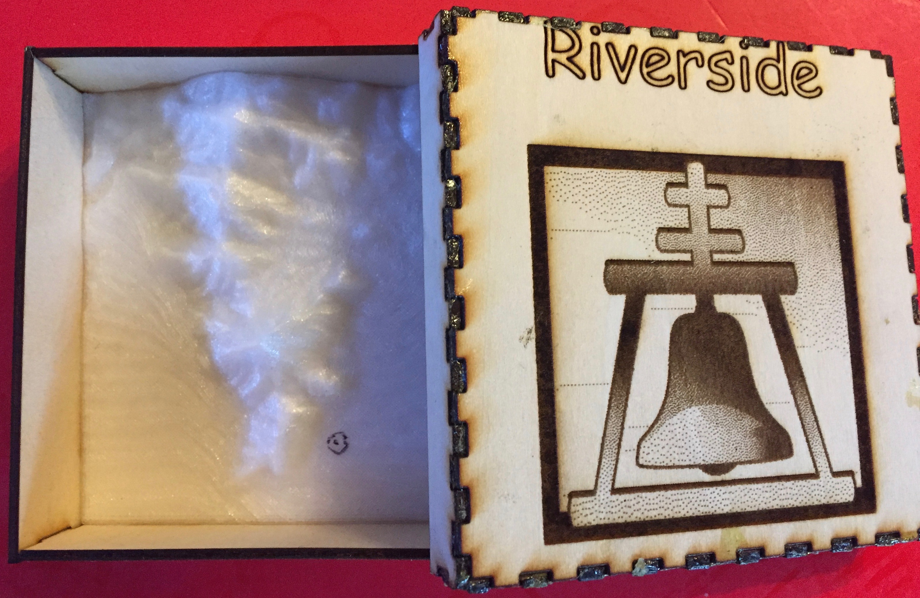
And I’m using the Laser Cutting capability to make Boxes (thanks to ‘MakerCase’ another Open source for Designs):

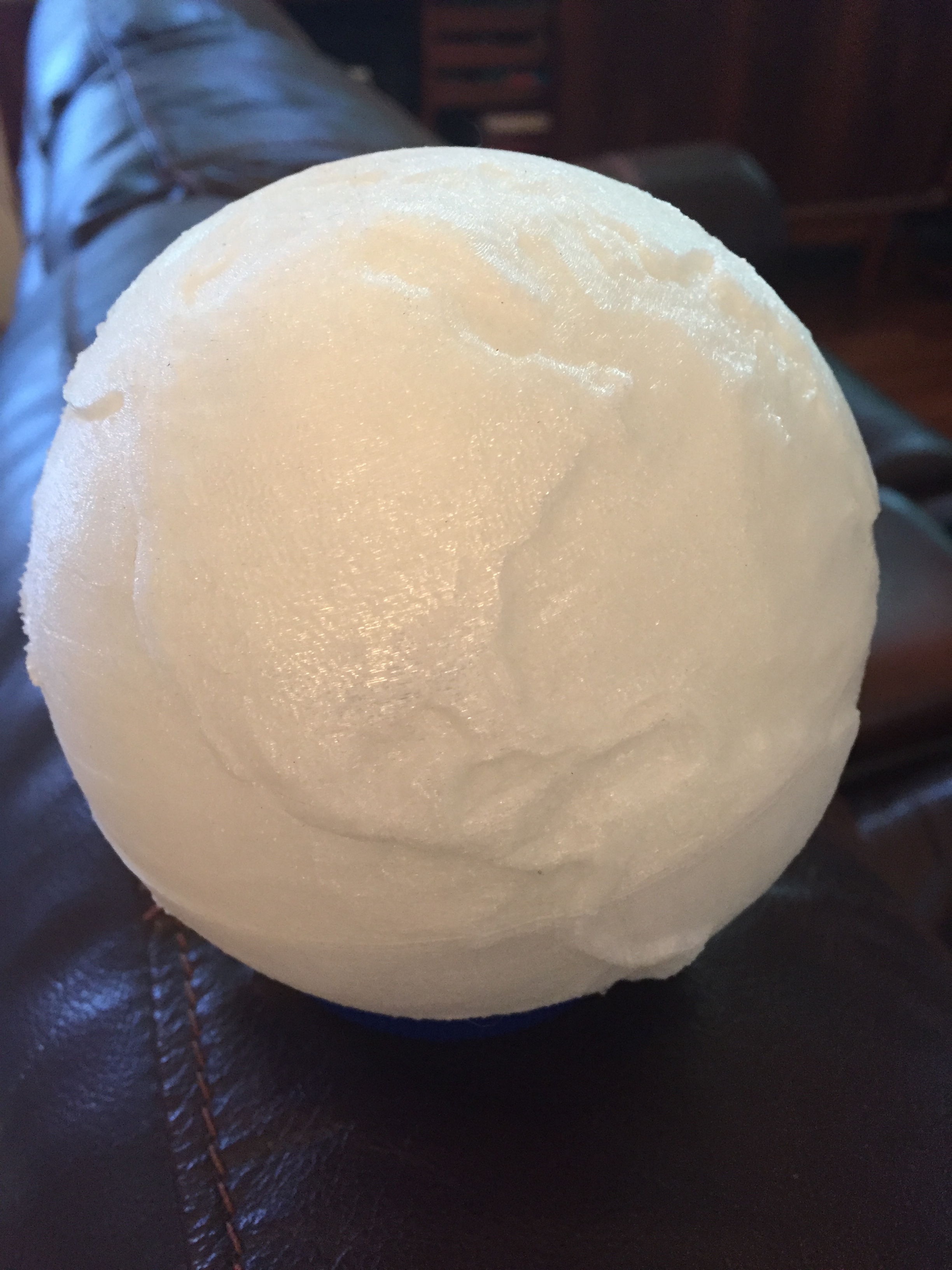
GLBox&MapRiversideBox&Map

And even more …

Globe

Escher

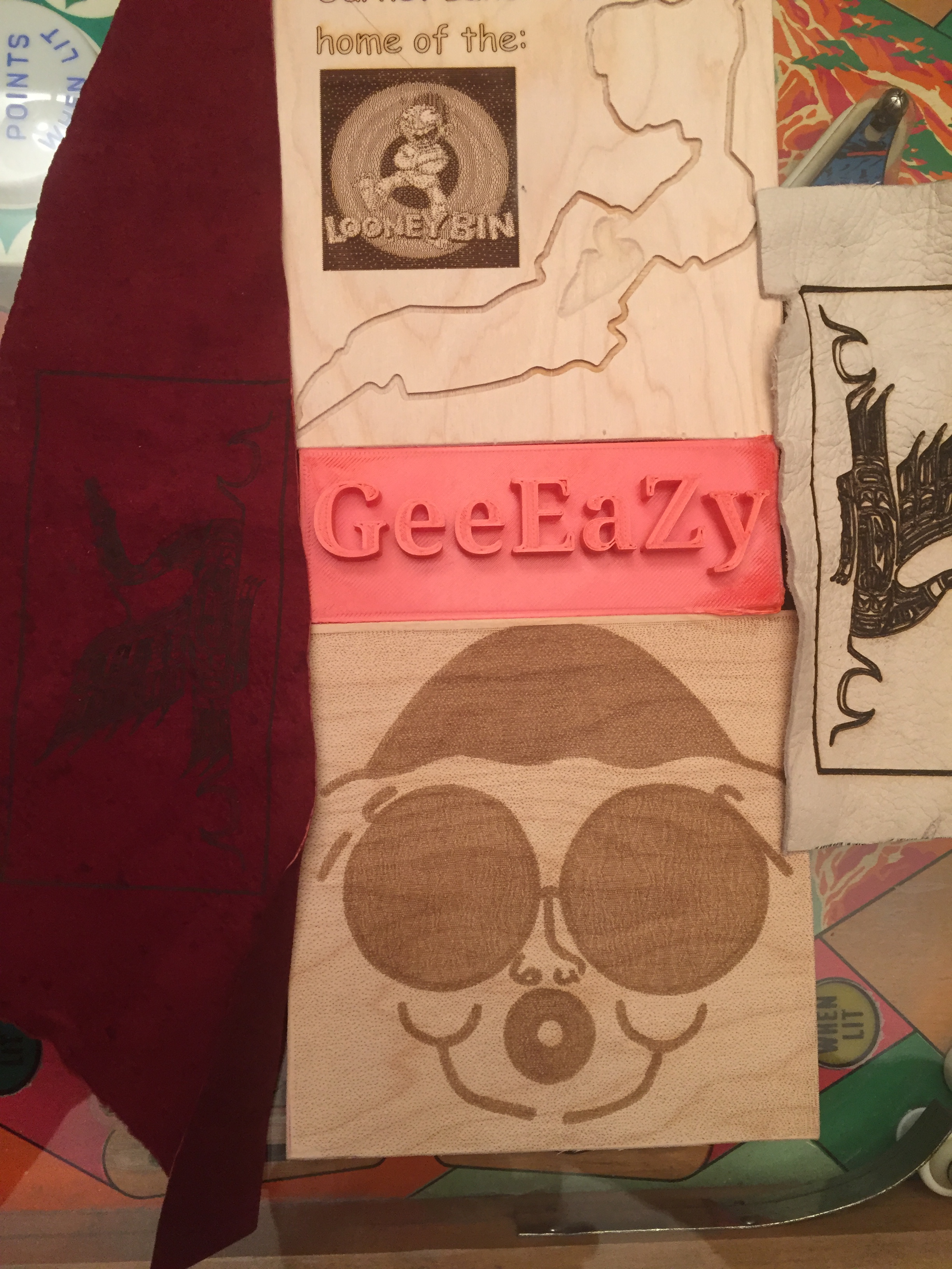
Etchings

LakeOutline

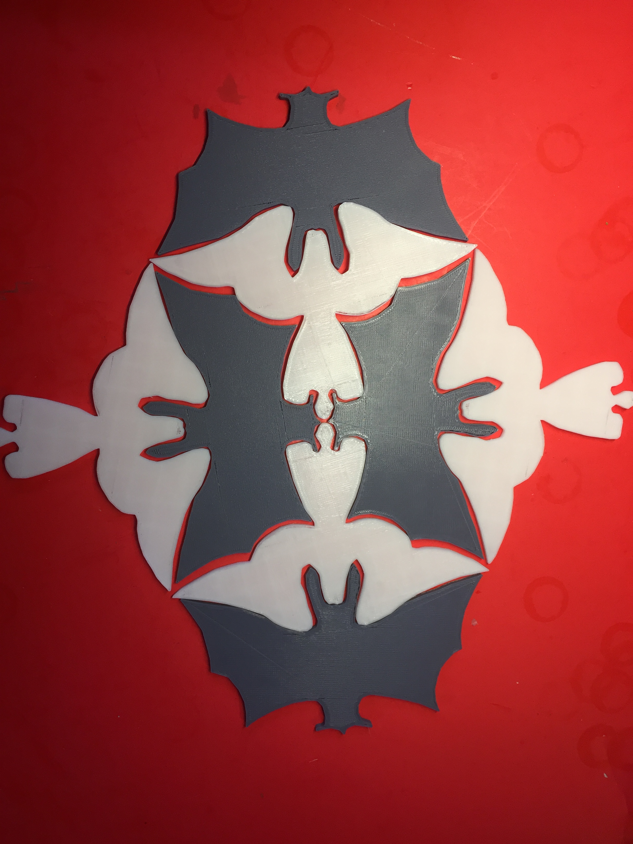
M.C. Escher Tiles

MakerEscher

Who knows what lies in the future?  I’ve barely touched the CNC Carving (Router) capabilities of my SnapMaker.

Here are some lessons I learned at the Prototype class and where to find Information.

Lessons Learned:

Be aware that there exists a thriving community of help and free stuff out there.  I think that you should initially use only free software and designs, then later select your professional package.

Consider the NATIVE language and Computer platform compatiblity of a software package and the system/computer (Apple or PC or …) you wish to use.  By NATIVE I mean, the platform upon which the software was initially developed.  Ported software is rarely complete and error free.  By PORTED I mean,  written in one language, then translated to another.

Consider the hidden got-ya’s of the commercial software world.  AutoDesk FUSION 360 will give generous TRIAL use; to students and hobbyists, BUT they encourage storage of your designs on THEIR cloud.  You may have to buy a years subscription (~$400) to have access to your designs. UNLESS you were able to save to local media.

Consider the file types that a software package will accept as input and output.  Consider your total package of software/hardware tools and the formats accepted throughout.

Be aware that there a 2 graphic representation types in current use – Vector and Raster.  The difference can be significant when representing an image.  JPG, BMP, GIF, PNG are some Raster formats, while SVG and DXF are Vector formats.

Be aware that while g-code is the standard format for CNC and 3D-Printer applications, not all machines will accept standard g-code – remember the old IBM language enhancements hype (PL/1 was their universal language).  A little aside; I worked for an outfit that bought into IBM’s pitch to use only PL/1, later to find that all their custom software applications would only run on IBM machines. And that it was impossible to get a competitive bid when wanting to upgrade to newer hardware (Married to IBM and PL/1 until someone (me) translated their software into Cobol and Fortran).

Be aware that access to home CNC devices is very new and is providing great opportunity for innovative uses and applications.  Keep an eye out for imaginative and exciting news and events – like MAKER Faires, MAKER books and publications.

Computer-Aided Design Tools:   Information is:  HERE and HERE

AutoDesk FUSION 360       Very Detailed and Complete – More than Needed

TinkerCAD                           Very Easy to Use and surprisingly Complete

InkScape                              Free and quite Adequate

OpenSCAD                           Free and Interesting and Different approach (programming)

Blender                                Free and Very Detailed and Complete – More than Needed

Mathematica                      Free and Interesting

SketchUp                             Free and Interesting

CADMapper                        Free and Interesting

Photo Editors:     Information is: HERE and HERE

InkScape                             Free and quite Adequate

Retina Engrave                  Interesting

Slicers:                  Information is:  HERE

IdeaMaker                           Interesting, with Repair Capabilities

Formats:                Information is:  HERE

STL                                       Stereolithography – 3D Standard 

SVG                                       Vector Graphics Standard

JPEG                                     Photo Standard – Raster Graphics

G-Code                                 CNC Standard (somewhat)

Sources:                Information is:  HERE

Terrain2STL                       Good Source of Map Data

TouchTerrain                     Better Source of Map Data

Thingiverse                        Great Designs

MakerCase                          Boxes made Easy

Filaments:           Information is:HERE

PLA                                       Biodegradable

CNC Devices:        Information is: HERE and HERE

Snapmaker                         Toutorials HERE

The approach I took to using my SnapMaker is as follows:

I am working on an Apple computer, the original SnapMaker, using only free software packages, and doing very basic operations.  What follows is a record of my discoveries.  These tools and capabilities may no longer exist, and more efficient ones are being offered regularly.  Please use the following as a guide only.

FORMATS

CNC formats

I started by identifying the FORMATS of the files required to communicate the information. I only considered 4 file formats (STL (stereolithography), SVG (Scalable Vector Graphics), JPEG (Joint Photographic Experts Group), and G-Code (computer numerical control programming language)).  The rest can wait for later.

3D printing requires an import of a STL format file.  STL is the standard format for communicating 3 dimensional information.  The engraving and carving requires an import from a JPEG or SVG format file.  JPEG is a common 2 dimensional photo (raster) format.  SVG is a common 2 dimensional image (vector) format.  The remaining format of interest is G-CODE which is the standard CNC (computer numerical control) format.  These are the only formats that I concerned myself with initially, there are many many more!

SOURCES …

Next, I concerned myself with where I would find sources of designs in the appropriate formats.  I will eventually create my own designs using CAD (computer-aided design) software, but I needed to see results now.

For 3D printing, a perfect starting source is THINGIVERSE.  Makers donate finished designs to this free website.  The designs are presented in STL format, so all I needed to do was download the files and then import them into SnapMaker.  I had a desire to make 3-dimensional maps of mountainous terrain.  I found TERRAIN2STL and TOUCHTERRAIN, two free websites that provide STL format files which import directly into the SnapMaker. 

I also wanted to make boxes using the SnapMaker laser cutting capabilities.  I found MAKERCASE another free website which produces SVG format files which import directly into the SnapMaker.  However a wrinkle developed when the box design assumed a Laser Cutting bed larger than the 125 mm by 125 mm bed of the SnapMaker.  More about that later.  

For laser engraving I found that PHOTOS (an Apple utility) would produce JPEG files from imports from my camera, my phone, the computer screen capture (CMD+SHIFT+3), Google images, and any other photo site.  Usually the editing required was accomplished in PHOTOS.  More about manipulations later.

SOFTWARE  …

I next searched for free software packages that would enable me to design products and export file formats compatible with SnapMaker.  The following diagram identifies the software packages which I found and used: 

MakerFormats

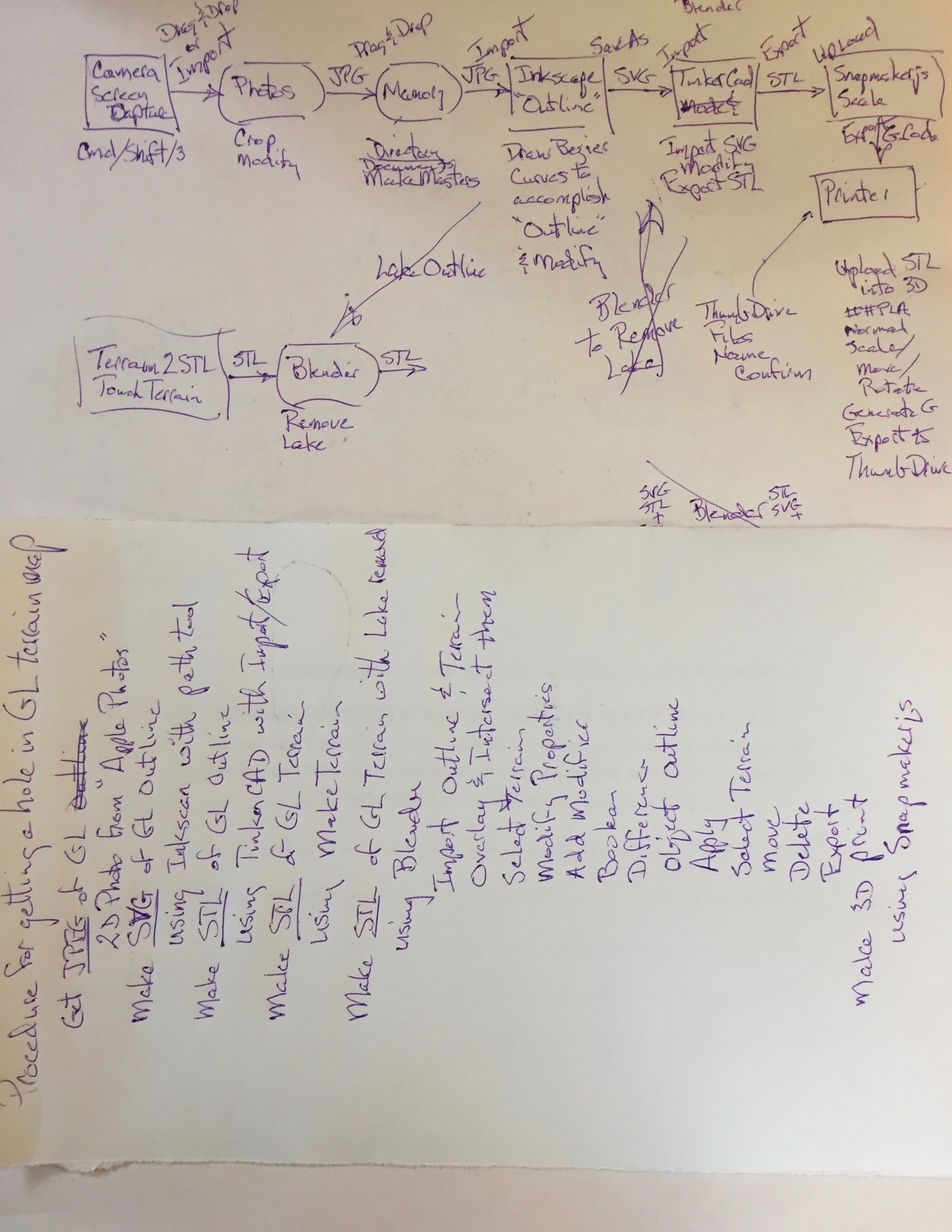
Rarely will you find a single package to make all the manipulations you desire.  The following flow chart identifies the steps and tools used to accomplish my 3D terrain mapping design:  

MakerFlow

I obtained the basic 3D map from TOUCHTERRAIN.  I next wanted to remove the water from the lake so that I could fill in depth information.  This activity required a lake outline, which I obtained using a Google Map image captured in JPEG format.  I imported the Google map into INKSCAPE where using the Bezier curves tool I obtained an outline of the lake.  The outline (in SVG format) and the Terrain map (in STL format) were imported into TINKERCAD or BLENDER where a Boolean difference was performed to accomplish the removal of the lake.  The resulting STL file was imported int SnapMaker for printing.  The outline (in SVG format) was converted to STL using TINKERCAD or BLENDER for editing to add water depth information.

The problem of restricted bed size mentioned above, was solved by ungrouping the components of the box (top, side, bottom) into separate SVG files using INKSCAPE.  

YOU

Your imagination and creativity will guide you to the appropriate, efficient and safe tool as experience grows.


Making Magic Squares

Leave a comment

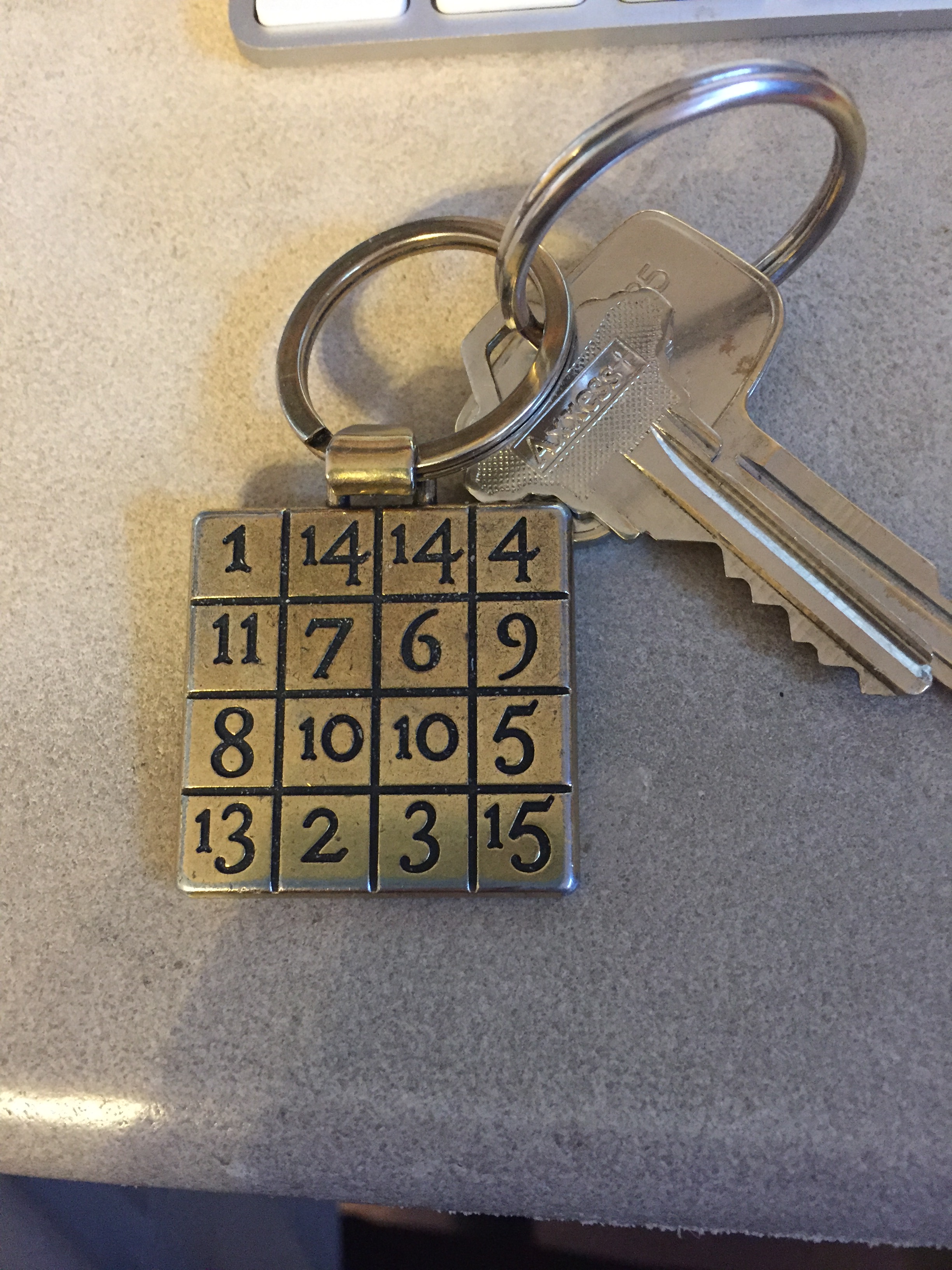
I carry, attached to my keys, a Magic Square; the original can be found displayed on the Sagrada Familia Basilica in Barcelona Spain.  See: a later post titled “Sagrada Familia, Barcelona” for further speculation about this particular Magic Square:

MagicSquare2

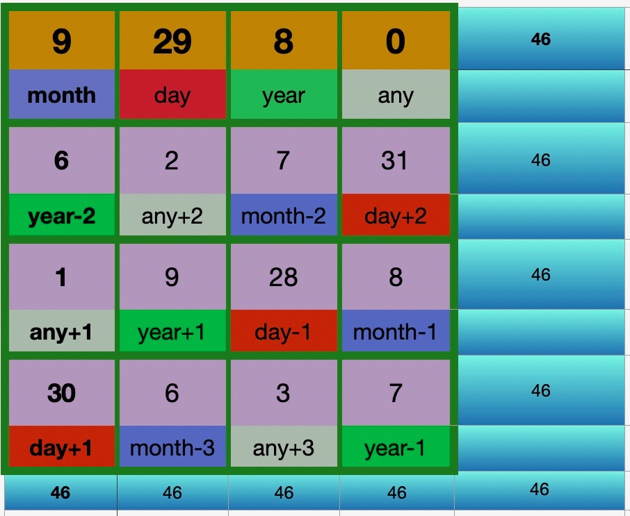
This square is considered magic because adding each row, or each column, or either diagonal, or other groups of 4 numbers yield the same sum.

Here is how you can use a spreadsheet to create a Magic Square.

As with all spreadsheets; the Columns are A, B, C, D, & E and the Rows 1, 2, 3, 4, & 5.    Now; we enter values and perform calculations in your Spreadsheet:

You may enter any values you wish into the cells in the first row; A1, B1, C1, and D1.

Then enter the following formulas into your spreadsheet:

E1 = A1+B1+C1+D1

A2 = C1-2,  B2 = D1+2,  C2 = A1-2,  D2 = B1+2,  E2 = A2+B2+C2+D2

A3 = D1+1,  B3 = C1+1,  C3 = B1-1,  D3 = A1-1,  E3 = A3+B3+C3+D3

A4 = B1+1,  B4 = A1-3,  C4 = D1+3,  D4 = C1-1,  E4 = A4+B4+C4+D4

A5 = A1+A2+A3+A4,  B5 = B1+B2+B3+B4,  C5 = C1+C2+C3+C4

D5 = D1+D2+D3+D4, and E5 = A1+B2+C3+D4

If you wish, the cells in the 1st row can contain your birthday and another number.

For Example: Here is a Magic Square using the birthdate of September 29, 2008 and 0:

MagicSquare2

Try it with some birthdates!  Then ponder how it all works.

Now try entering other numbers, like zeros and negatives into A1, B1, C1 and D1.  Maybe it will be clearer now how it all works.

There is more information about Magic Squares HERE. You may notice that the Wikipedia article contains a ‘Birthday Magic Square’ which is very similar to your spreadsheet.  It uses the date convention of Day/Month/Year and it contains the Century value, yet it is using basically the same method of construction as your spreadsheet.

Incidentally; if your birthday is 5/4/8 (May 4, 2008), you may have noticed that South American relatives send their birthday wishes a month early on April 5th.  A reason for this can be found HERE, A very confusing lack of standards, which has led to many misunderstandings!

HERE is a web site that presents a Mind Reading trick using Magic Squares.


Alternative Energy

Leave a comment

Lately I’ve been thinking of other ways to satisfy my power needs.  At our home in the Mountains we are very close to being “off the grid”.  We have our own water supply, our own sewage system, we could burn wood exclusively for heat, but we are far from being self sufficient.

Electric power is critical for our lifestyle.  

We have a stream flowing through the property, which could supply some power following rain storms or during Spring run-off, but continuous supply of power from it is not possible.  We have limited Sun access for much of the day.  We have lake breeze many afternoons.  We have tremendous temperature differences during the Winter, between Air temperature and Lake temperature.  Geothermal is being used by neighbors via old wells and heat transfer systems.

The hope is that with sufficient energy storage (perhaps my electric car), using the sources available we might be able to be “off the grid”.

Now … how do I turn that hope into reality … hum … 

For many years people around Mendocino county, California lived remotely with plenty of resources to explore off-the-grid existence.  Much of their effort was recorded and directed by a magazine Home Power.  I look forward to searching through the archived issues in the local library.

I have obtained a WaterLilly and will explore it’s use next year.  I might even tow it behind the canoe to charge the cell phone (which probably would have no service bars).

We have installed a new fireplace insert which makes the living room very comfortable.  A additional feature is the Fireplace Fan which requires no external power and is driven by converting fireplace heat to electrical energy and using that to turn two fans.  Hopefully more than the living room will be comfortable.

The concept of Gravity Weight attracted me sufficiently to install a series of LED lamps powered by a falling weight.  We get about 20 minutes of light per pull.  You could get a lot more time if the weight were falling from a tree (and the chain were long enough, and …)

The Stirling Engine represents for me the most promising alternative energy source for small applications.  The temperature differences that we have, particularly in Winter, offer possibilities for future exploration.  The video guy in the link above, is Bill Nye (The Science Guy) of Science Education fame.  If you’re either too old or young to remember him it would be worth your while to Wiki him.

A Mendocino Motor is just too beautiful to ignore.  The combination of Solar energy and magnetic levitation is very exciting.  An example of the kind of Engineering you would expect to find in Mendocino County, California, USA!

I have a rotating wheel device using a Memory Wire for power.  This wheel a very fragile structure requiring short (duration and intensity) use.  A robust application is the Muscle Wire (spring) robotic muscle simulation.  This video discusses in flowery expressions the possible future where Nitinol plays a primary role in energy production. While this video attempts to explain the atomic structure responsible for the memory ability.

The possible uses are so numerous as to be “low hanging fruit”.

All of these approaches hold promise of ‘scaling up’, but in their present state, there are trade-offs that are not that easy to make.

Here are videos of my explorations thus far:


Toilet Hack

Leave a comment

Having seen a hand rinse toilet hack at a friend’s, I decided to see what action I could produce with the falling water.  More to come!

Toilet Hack

Previews of coming attractions:

Bamboo water wheel with figure turning crank

Water wheel turning generator which lights a small LED

Variations on Hydropower useage


Laboratory Test Equipment

Leave a comment

I have been attracted to the numerous laboratory test equipment that I came in contact with while being an engineer, but couldn’t justify purchasing them.  Recently I came across reasonably priced ‘build your own’ kits, and have enjoyed playing with them:

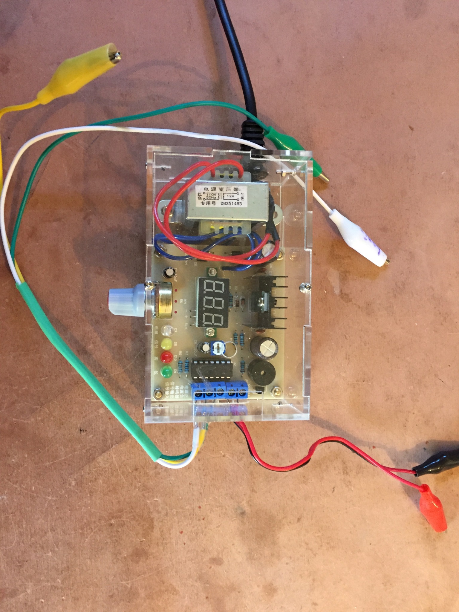
PowerSupply

The Power Supply above will provide 0 to 12 volts DC to the red & black clips, added features are a continuity tester with buzzer (green), a square wave generator (yellow), and a logic probe (white).  And all for about $14.

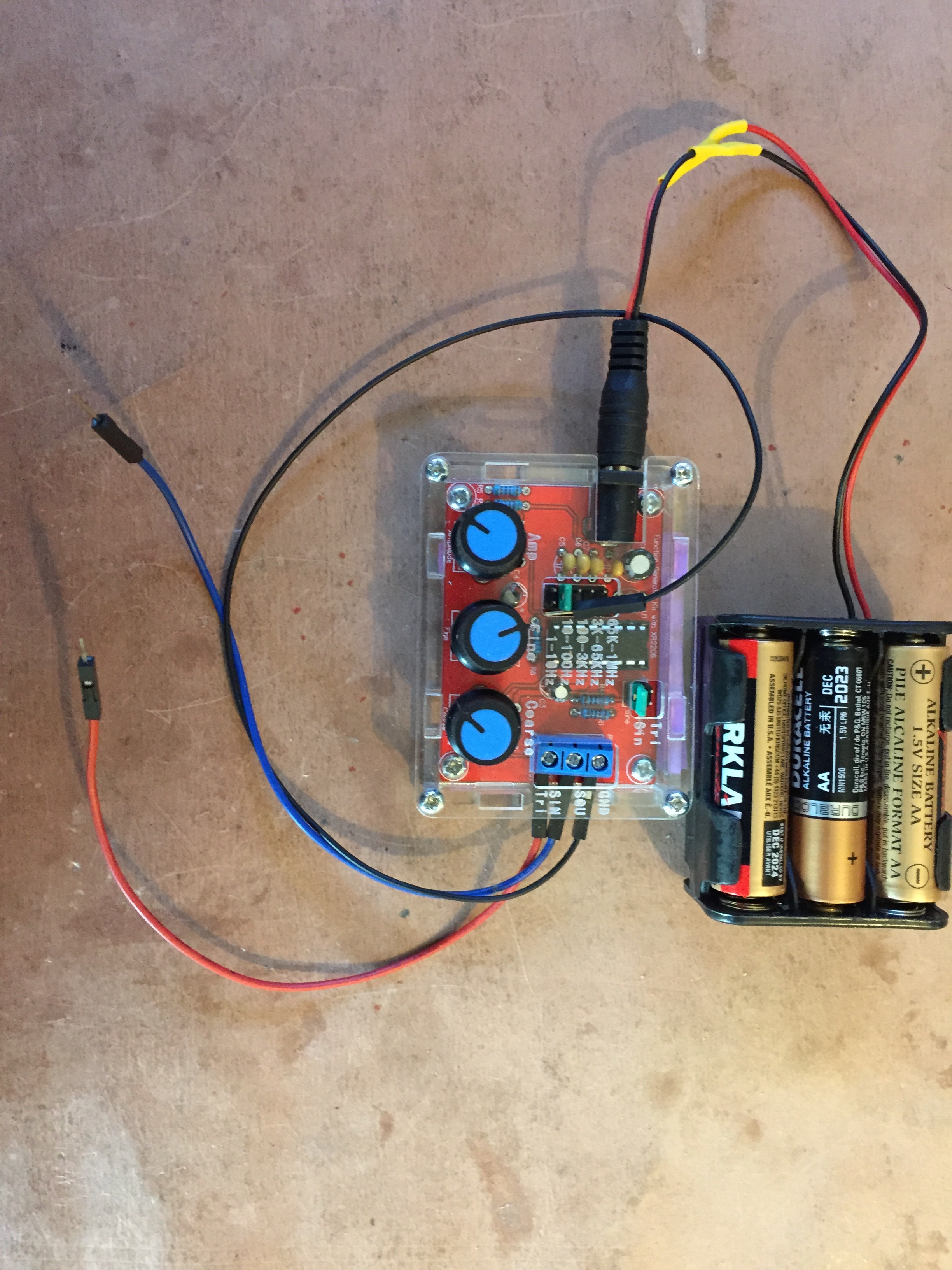
SignalGenerator

The signal generator above will produce square, sine, or triangular waves with frequencies from 1 to 1MHz.  For approximately $13.

Oscilloscope

The oscilloscope above also functions as a frequency counter and will display a single channel input.  For approximately $20.

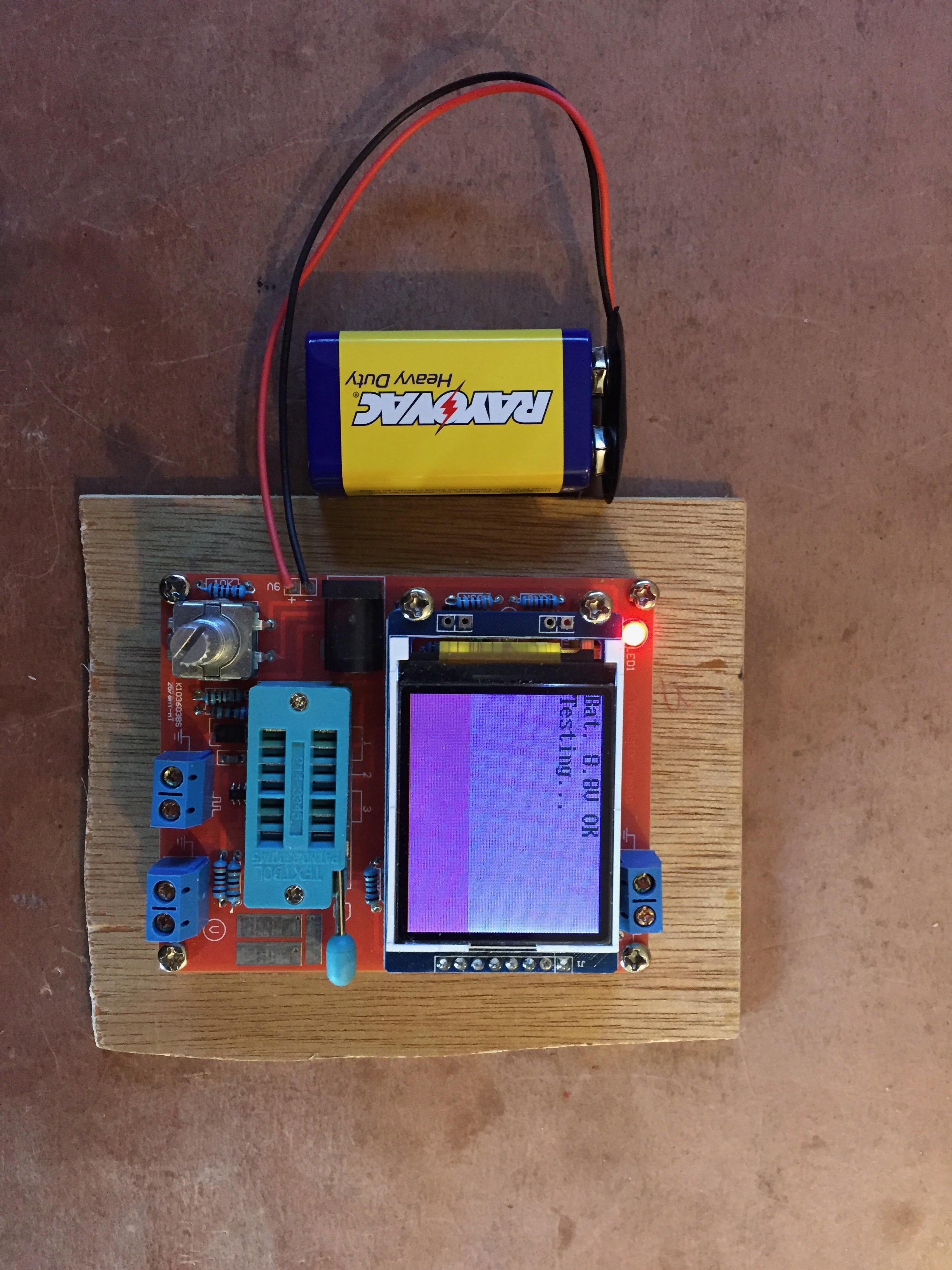
ComponentTesting

The component tester above will measure resistance, induction, capacitance, frequency and voltage while testing transistors.  Additionally it will generate square waves and a pulse width modulation signal.  And all for approximately $15.

I’ve had the fun of building them and am now looking for uses.

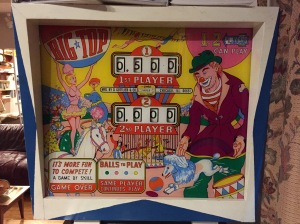
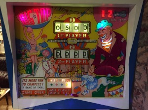
Big Top Pinball

Leave a comment

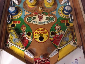
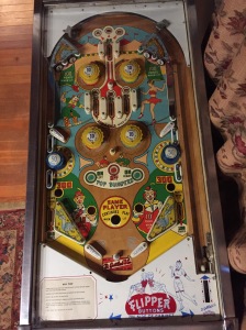
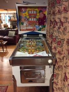
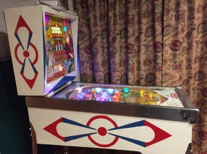
This year I refurbished a 1964 pinball machine.  It’s a New York machine, so it gives ‘Extra Balls’ (Continue to Play) instead of free games.

back

backlighted

I haven’t included all of the back-glass lights.  A previous owner painted the inside of the back-glass with NON-translucent paint, so back lighting presents an unattractive display.

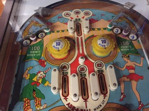
upper

mid

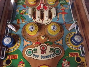
lower

The playfield is very clean, with a few wear spots, and is complete.  I have added new rubber and replaced all the lamps with Led’s.  The four flippers made Merle happy, allowing me to move it from the garage to the dining room.

play

front

New legs and 3 months of fiddling produced a machine that is fully functional.

side

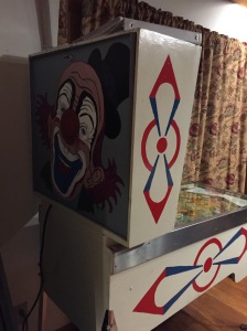
A previous owner painted the cabinet, to the original design.  The work is not professional quality, but presents very well.

backside

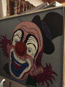
clown

I added the clown artwork to the back door.  The image was copied from the internet with no credits available, although the artist is probably Jacqueline Macou.

The only hacks that I’ve added so far are a switch to silence the bells, and a post between the bottom flipper.  The post is appreciated by all my non-professional players.

This Winter it will be housed in an un-heated house in the Adirondack Park, upstate New York.  The temperature extremes are large, but the humidity should be low.  I’m keeping my fingers crossed and will be anxious to play it next Spring.

This is my 3rd renovation, all electro-mechanical Gottlieb machines.  I wouldn’t say that I’m hooked, but I am looking for and EM ‘Home Run’ or ‘Playball’ for my daughter’s home.

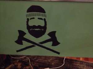
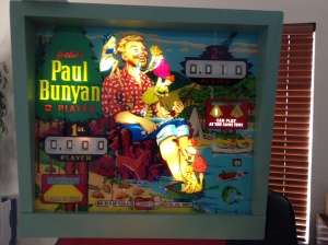
Paul Bunyan Pinball Machine

Leave a comment

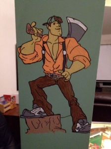
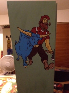
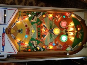
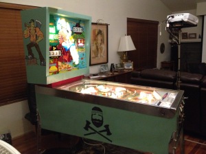
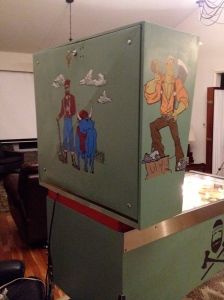
My current passion is to restore a 1968 Gottlieb electromechanical (EM) pinball machine to the theme of Paul Bunyan.  We chose this machine primarily because it has 6 flippers, giving us a better chance to keep the ball in play.  After searching for six months or so, a pinball enthusiast (Cliff Rinear) I had contacted, spotted one for sale near Modesto California.  After looking at a few pictures and talking with the ‘owner’, I gave him $325 sight unseen.  Jessie and I drove up to get it, in my Prius.  Seeing it, I was having serious second thoughts and had I not already purchased it, …  It had been stored for 30 years without the playfield glass or a back cover, the paint flaked off in our hands when we lifted it.  After a month or so the cosmetic part is essentially complete.  Most of the game features work.  I’m hopefull!  Here are some pictures:

First my copy art … there are those purists who will say that I have gone beyond the acceptable limits of responsible restoration.  Oh well …

The Right side of the Wedge.

WedgeRightSideArt

The Left side of the Wedge.

WedgeLeftSideArt

The Back of the Wedge.

WedgeBackArt

The Sides of the Playfield.

SideArt

And now for the machine:

Wedge

Playfield

RightSide


BackRight

I have spent the last year bringing it back to life.  EVERY feature now works!  All lights are switched to LEDs.  The coin chute works, but is not required.  All free game conditions work.  Now I’m customizing.

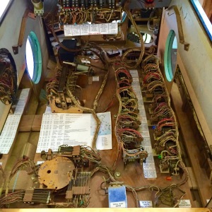
Cabinet Floor

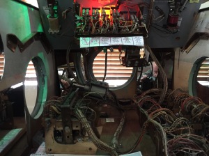
RearPortholeInside

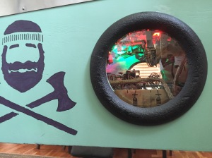
RightPorthole


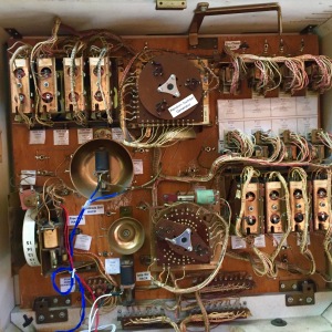
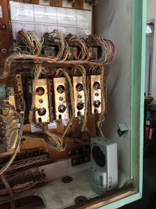
You can see the portholes and mirrors that are added for spectator viewing.  I had considered making a transparent cabinet, but decided that it was beyond my capabilities.  I’ve added labels to all major components and a few LEDs to give a small light show.


FlipperHacks

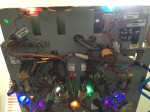
From this view of the Playfield bottom you can see the area of my flipper hacking.  The purpose of the next phase is to make the machine handicap accessible.  The first step is to add a Flipper crossover, which causes all 6 flippers to respond to either flipper button.  That hack is complete and can be seen upper right in the photo.  I love using knife switches and have used them in all hacks to date.

Behind Wedgehead


This view of the back of the wedge head shows some additional hacking that I’ve done.  I have a Tens and Hundreds bells hack that permits silencing those bells.  There is a free game hack for bypassing the 10 cent coin chute.  All of my hacks are reversible with the throw of a knife switch.

MusicHack

My most recent hack is to add audio to the playing experience.  The audio is provided by a hacked security device, sitting in the lower right of the picture above.  This Recorder/Player is attached to a New contact that I added to the 1000 point relay.  When a 1000 point addition is achieved the recorder plays a version of “The Lumberjack Song” by Monty Python:

I’m a lumberjack and I’m OK.  I sleep all night and I work all day.

I cut down trees, I skip and jump. I like to press wildflowers.

I put on women’s clothing and hang around in bars.

I cut down trees, I wear high heels, suspendies and a bra.

I wish I’d been a girlie, just like my dear Mamma.


I’ve added several additional features:

A mild verbal chiding has been added following a TILT.

Sip action is complete.  Sip and Puff are alternative choices – you can’t have both at the same time.  I went with Sip on both Sensors, but changes are easily made

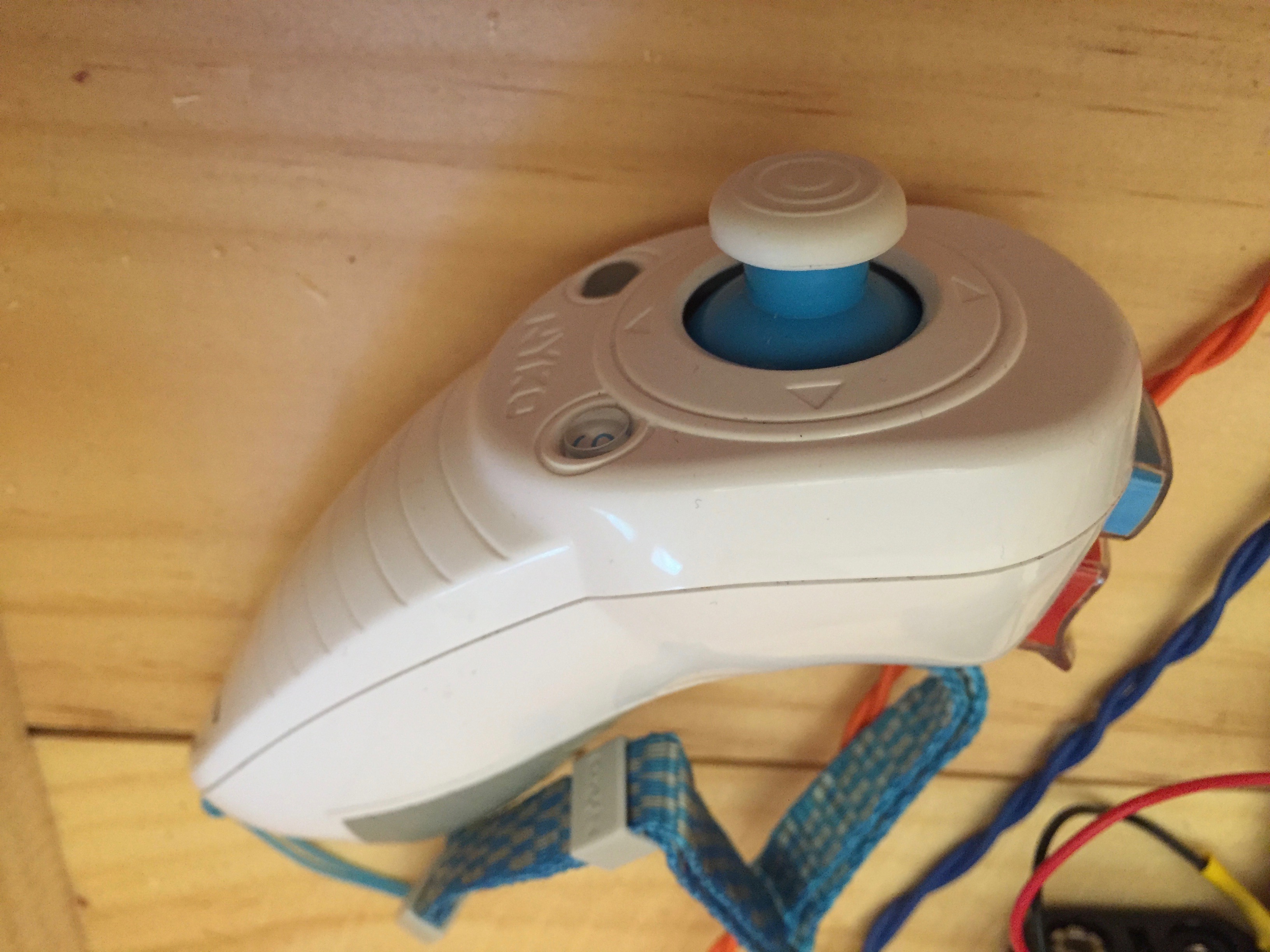
Wii Nunchuck control has been completed.  The accomplishment of this feat involved using a Arduino Pro Mini with software.  I used the switch and joystick actions to control the right and left flippers.  I made no use of the 3-axis accelerometer data (see what’s next list below).  The software has the values and they will be used in other applications.

Here are a number of images showing the accomplishment of remote control of my Pinball machine:

UmbilicalBox Top

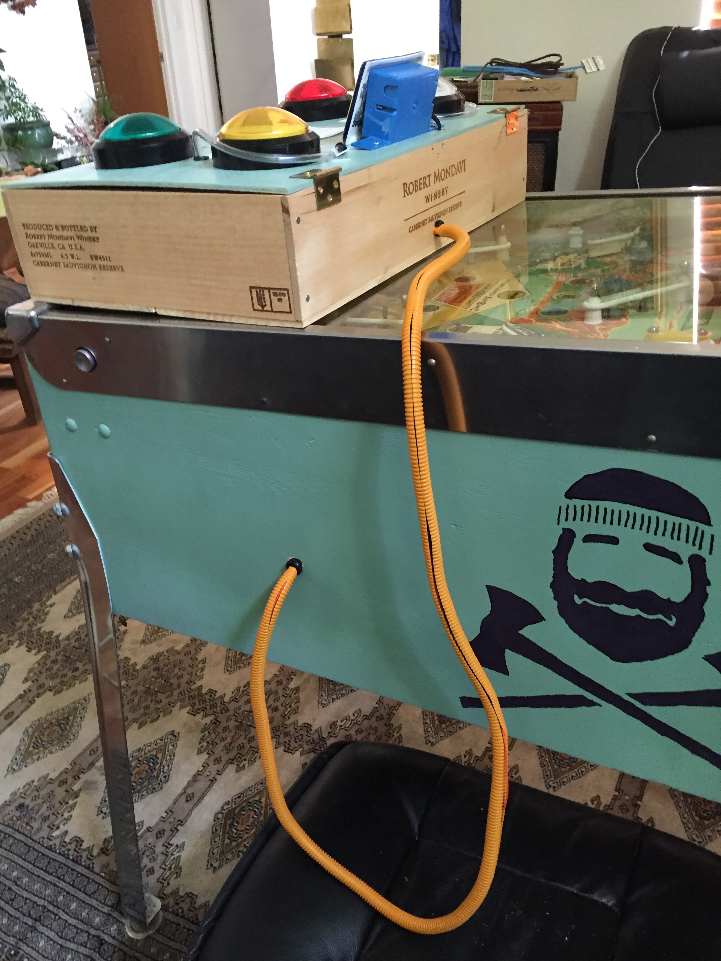
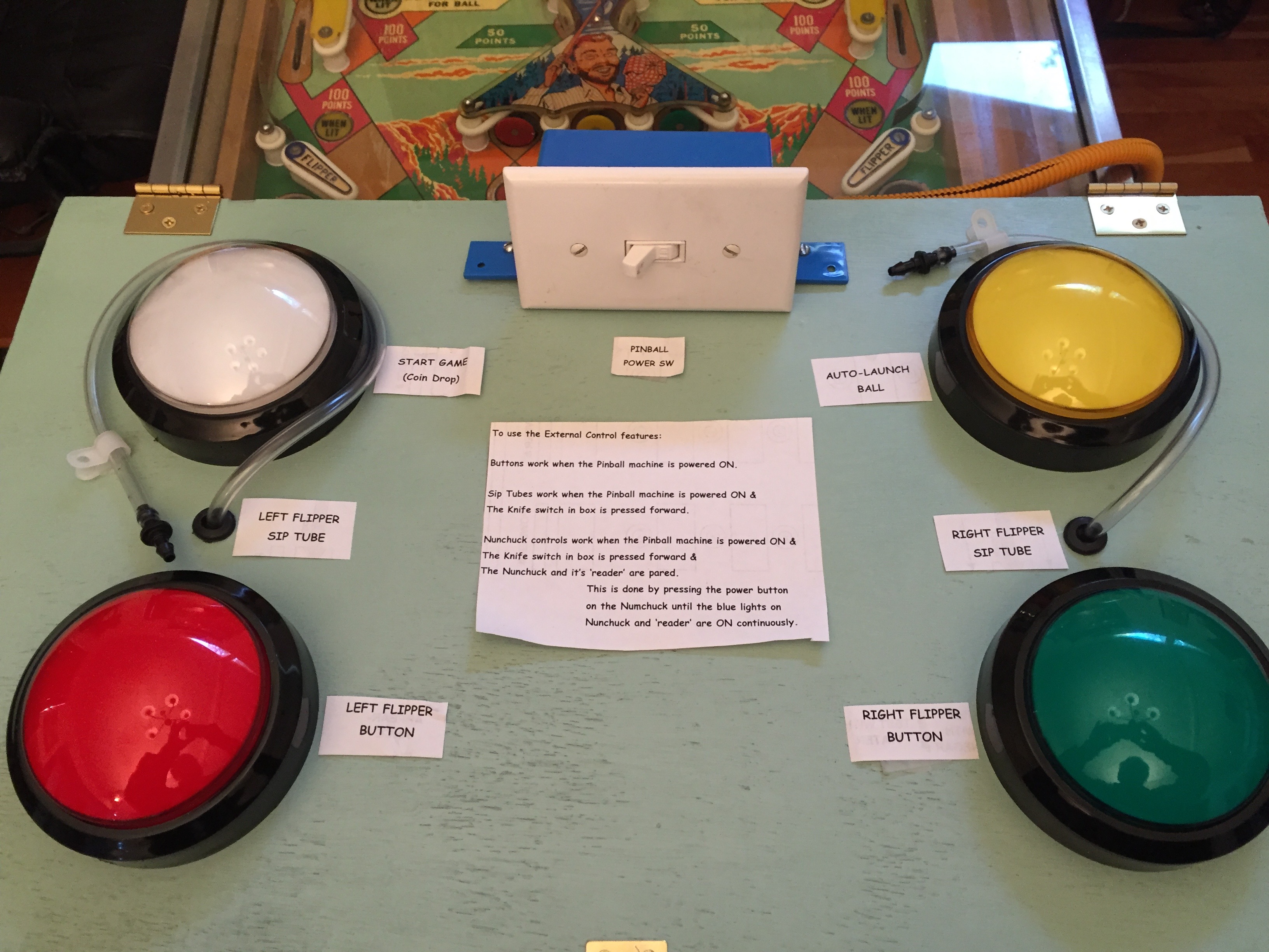
The Red and Green buttons and associated Puff/Sip tubes control the flippers, the White button controls the Replay Button, and the Yellow button will control the ball plunger (yet to be implemented).

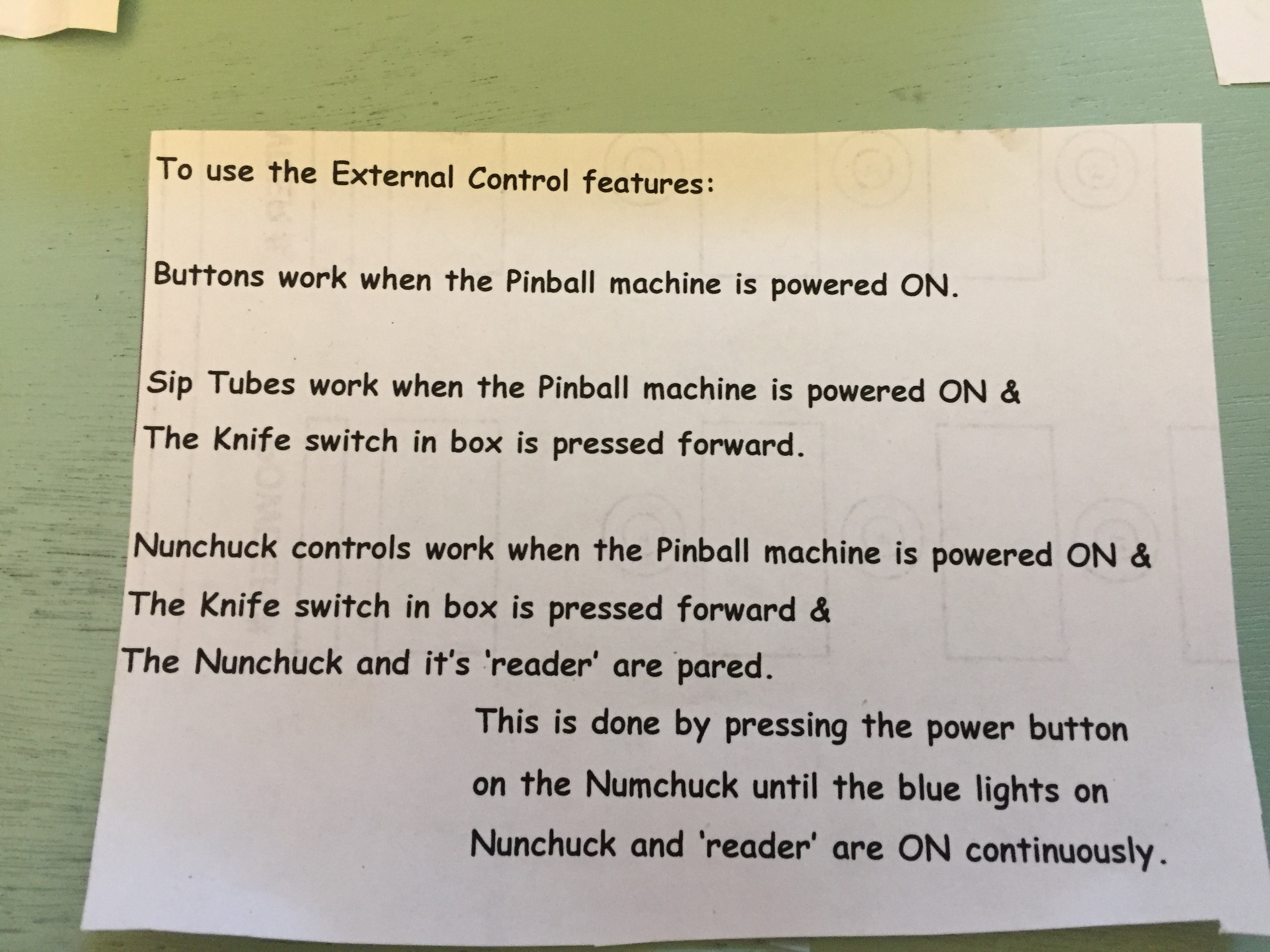
Instructions

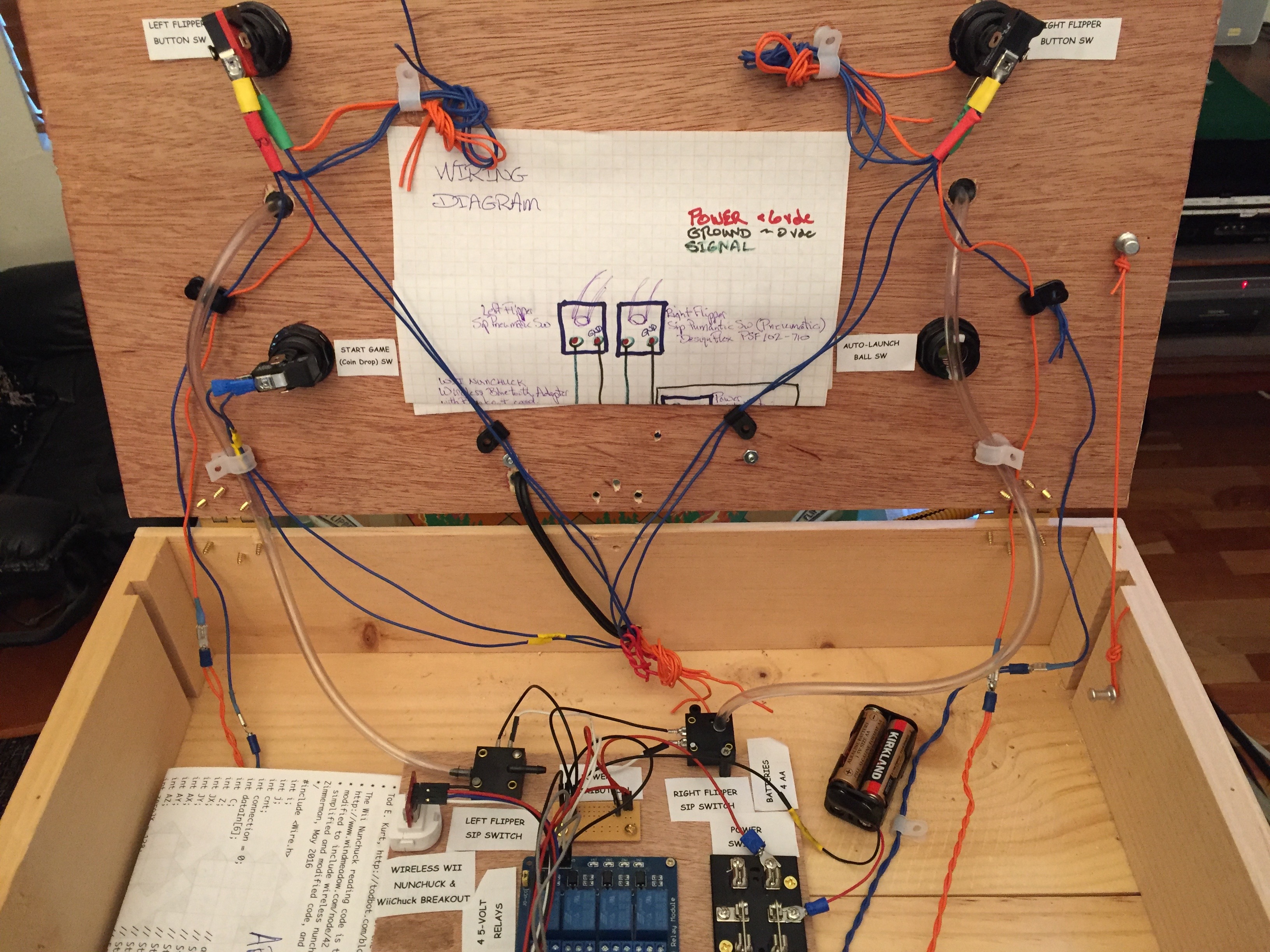
Inside the box:  Only the fearless dare to tread here …

Inside BoxWiring DiagramIMG_1083Software

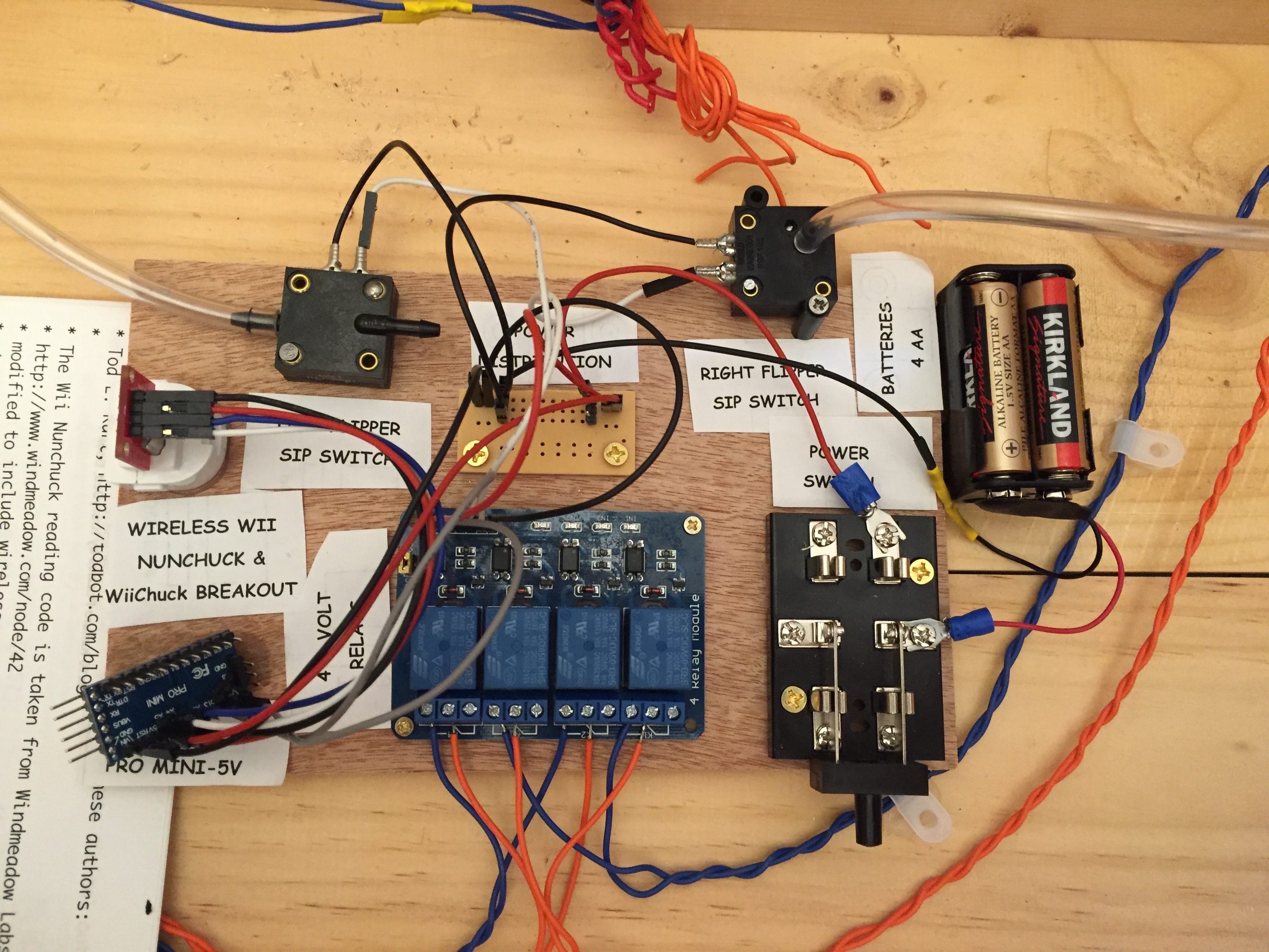
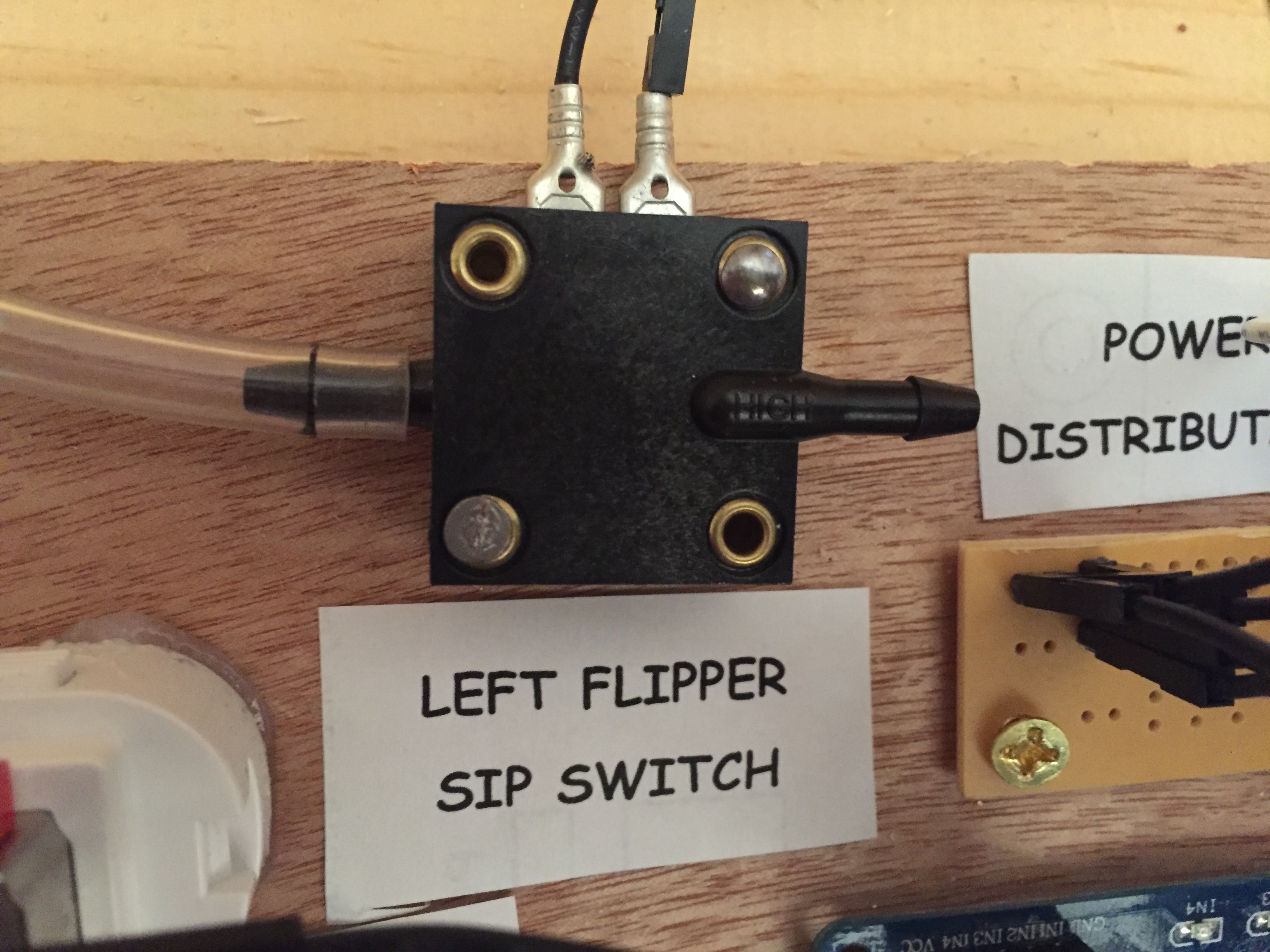
The hose connector to the Right is for Puffing (a higher pressure)

Left Sip

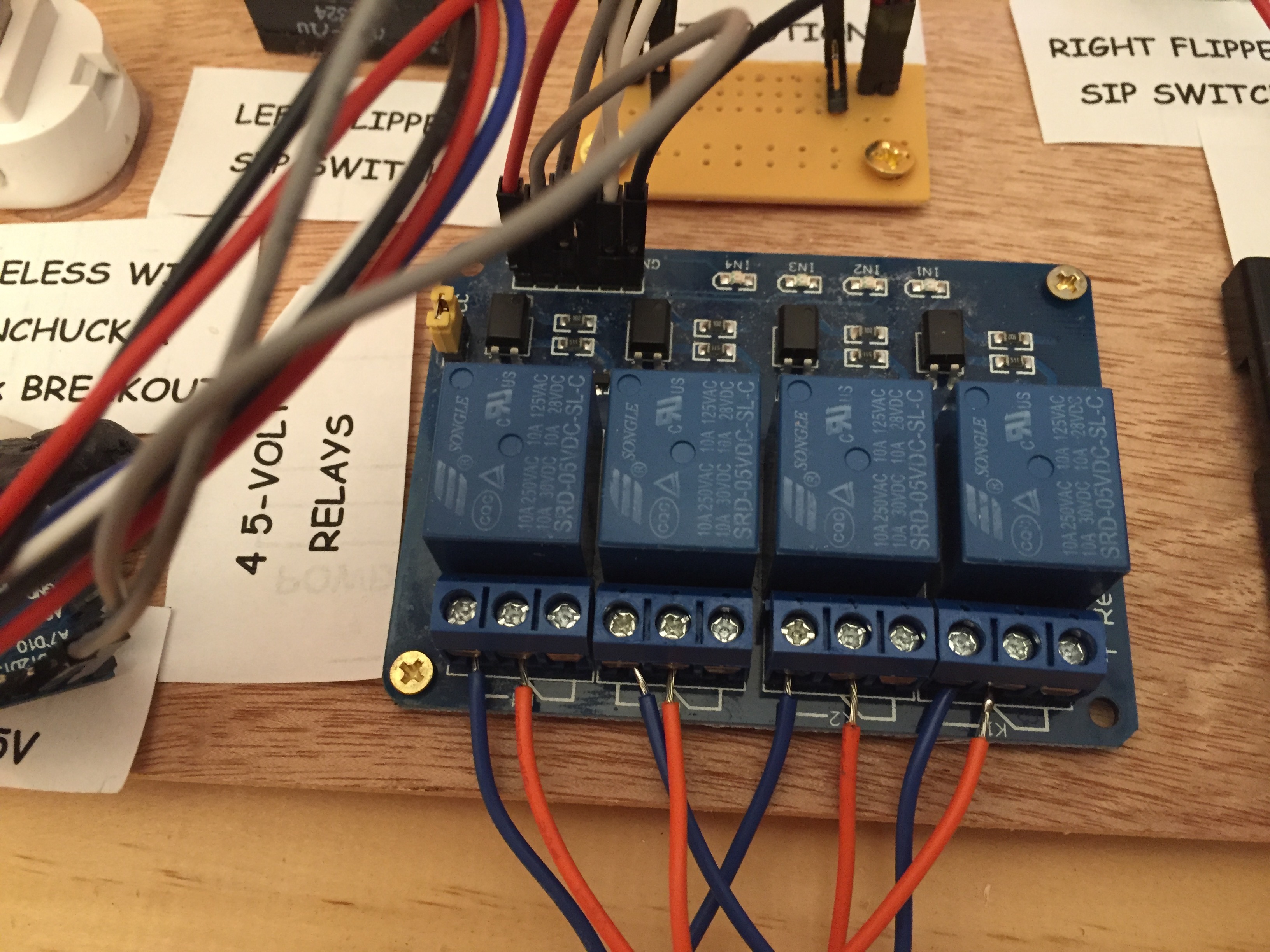
Inputs and Outputs of the Relays are indirectly from the normal Flipper switches.

5-Volt Relays

Nice Remote Control Device, via BlueTooth.

NunChuck

Well I haven’t done any of the above, but I did come across a sound sensor and decided to add sound triggering of the flipper control circuit.

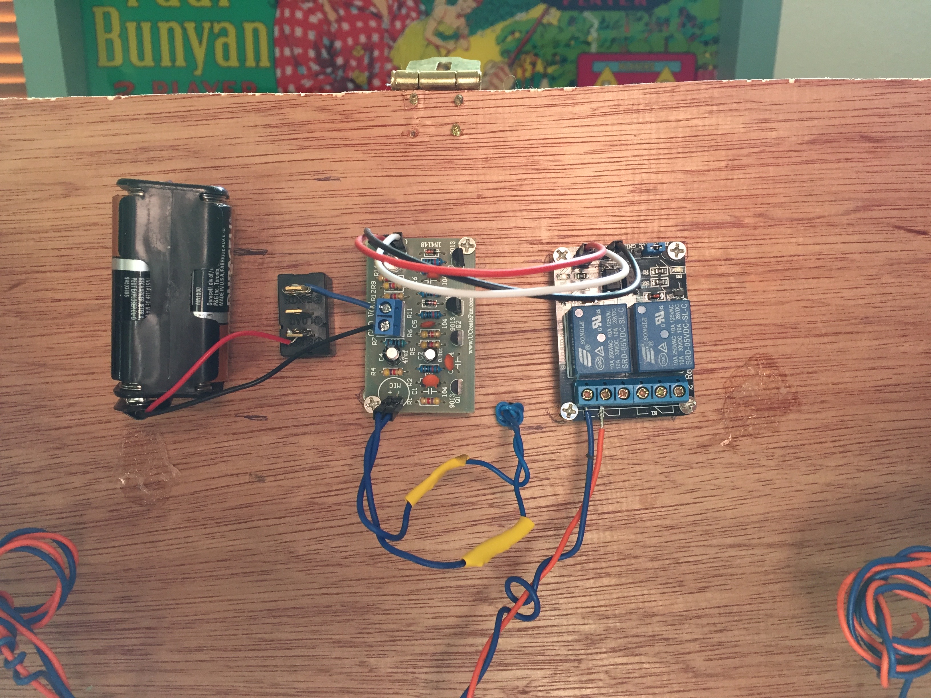
SoundBoard

The sound board with power and relay controls is installed.

Speaker

The sound capture is installed, but the whole thing does not function properly.  I’ll have to ponder this one for awhile.

Next hacks:

I’ve found a IR sensor that will respond to any click on any remote control, I may install that next.

I’ve been considering adding head-tilt as a control of the flippers.  It would be easy to implement, actually only 2 lines of code since the accelerometer values are read in with all the others.  The problem is that the accelerometer values are very sensitive to giggling and random movement.  Filtering would be the answer, confirmation, or smoothing, or …  Once this is working, other movements can be added; like winking, or …

I want to add a solenoid and hardware for remotely actuation of a ball plunger; without hopefully interfering with the manual plunger.   It’s not as if it’s never been done.  There are a number of Stern machines that use a Auto-Launch assembly.  I can get a new one for $80, but am advised that considerable modifications to my cabinet may be required.  Not that I am haven’t done that already.


Play NIM

Leave a comment

For my Christmas gift to young people next year (2020), I plan to put together a Play Nim game package.  The Box will be one that I produce with my new laser cutting skills.  The instructions and explanation will be the following:

PlayNIM

Since High School days I’ve had a fascination with the game of NIM.  I’ve tried on several occasions to write a program to play the ‘perfect game’, but for one reason or another didn’t make it.

Recently I was having fun with a Arduino MEGA 2560 microcontroller.  I started with a UNO board but quickly found that it didn’t have enough inputs for my needs.  The MEGA has 54 digital inputs and 16 analogs, that should hold me for awhile.

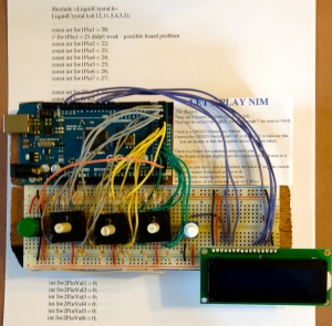
Now I’ve done it!  Here is a picture of the hardware side of the solution:

PlayNIM

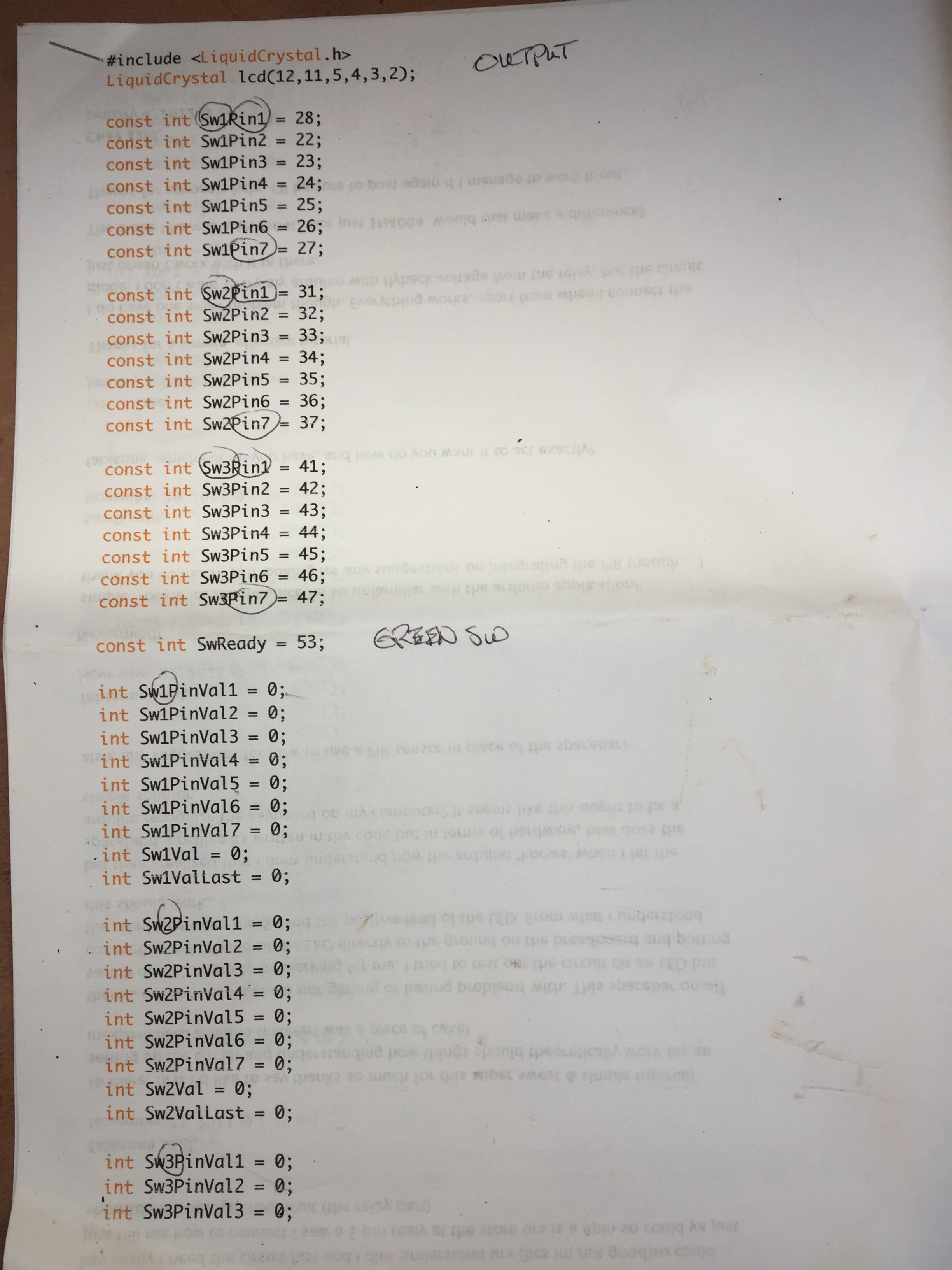
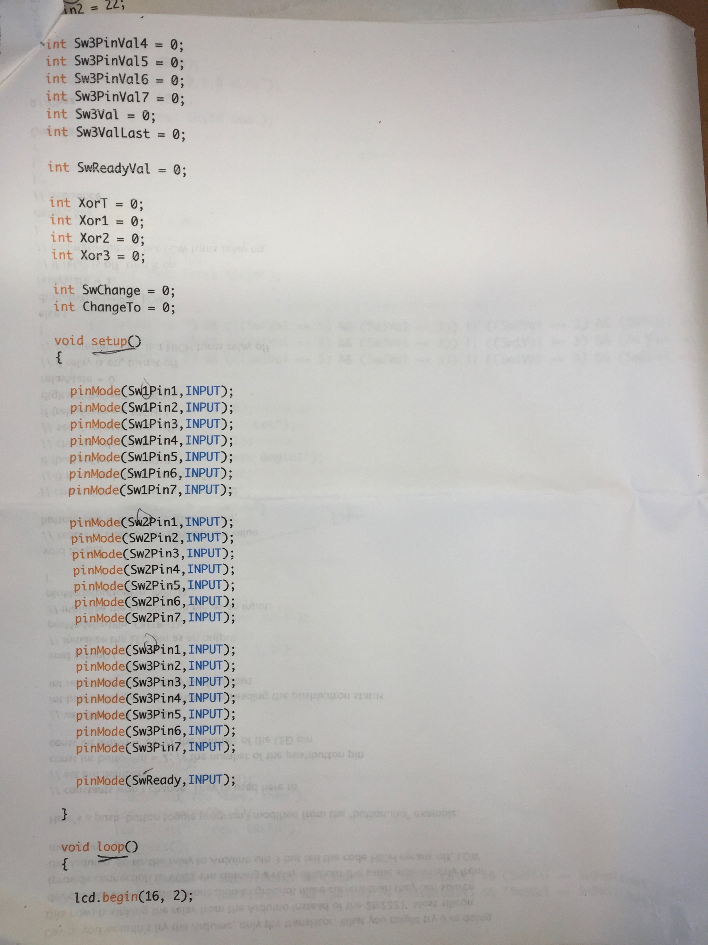
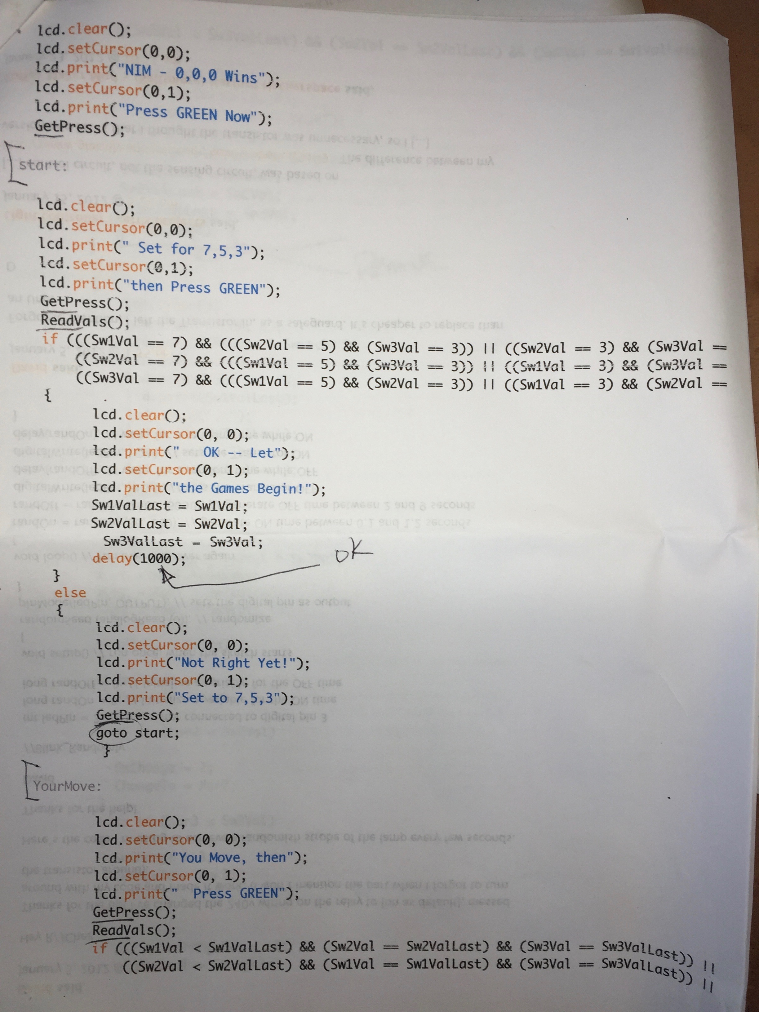
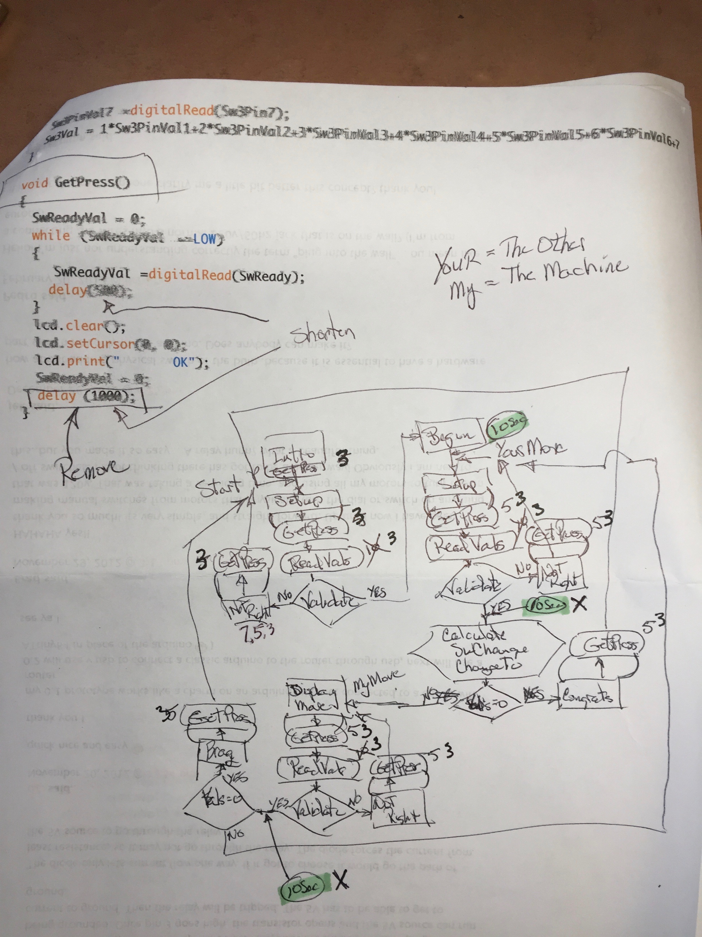
The software side is harder to show, but it works!  Sorry, but this is all I have to show:

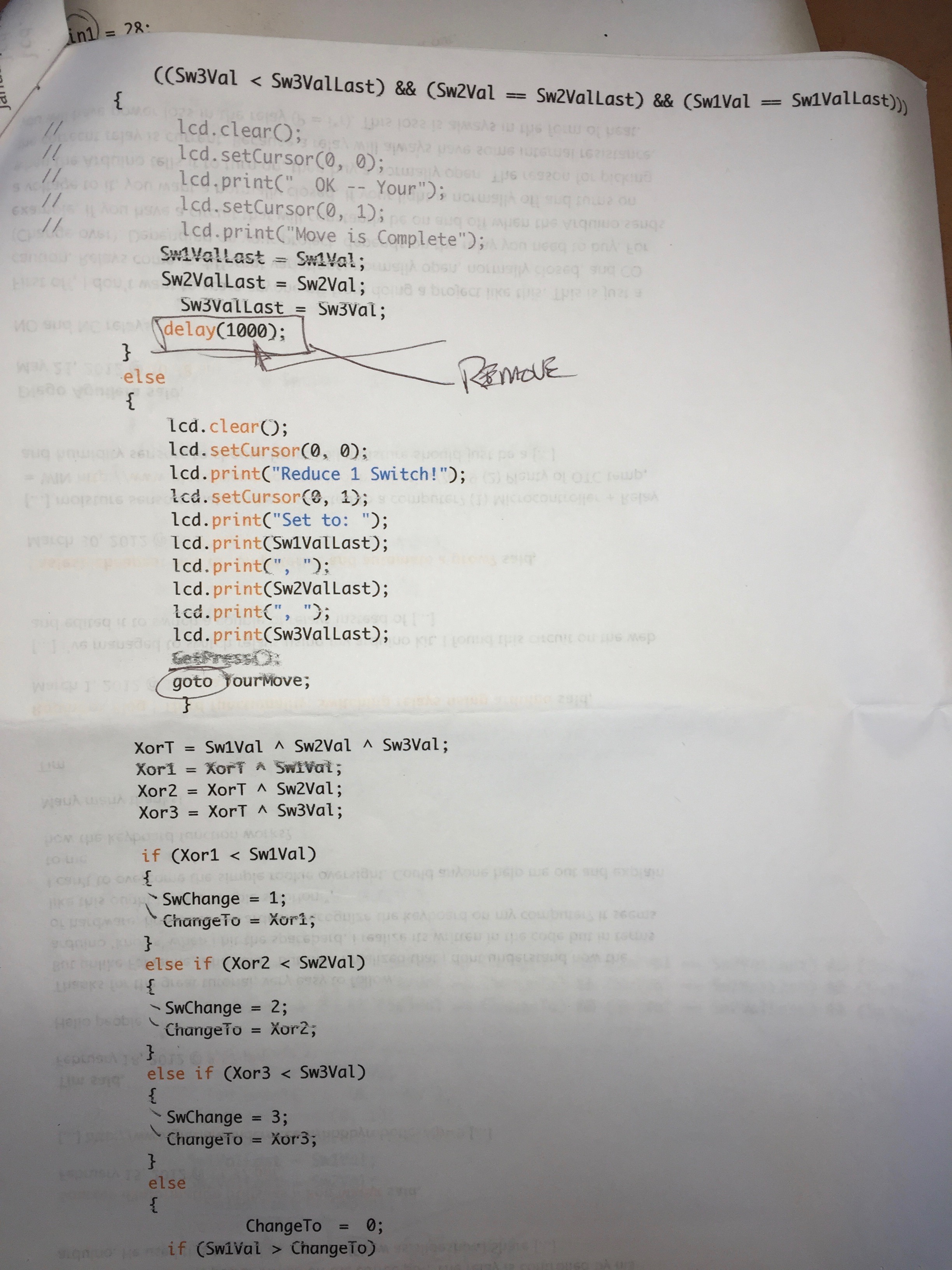
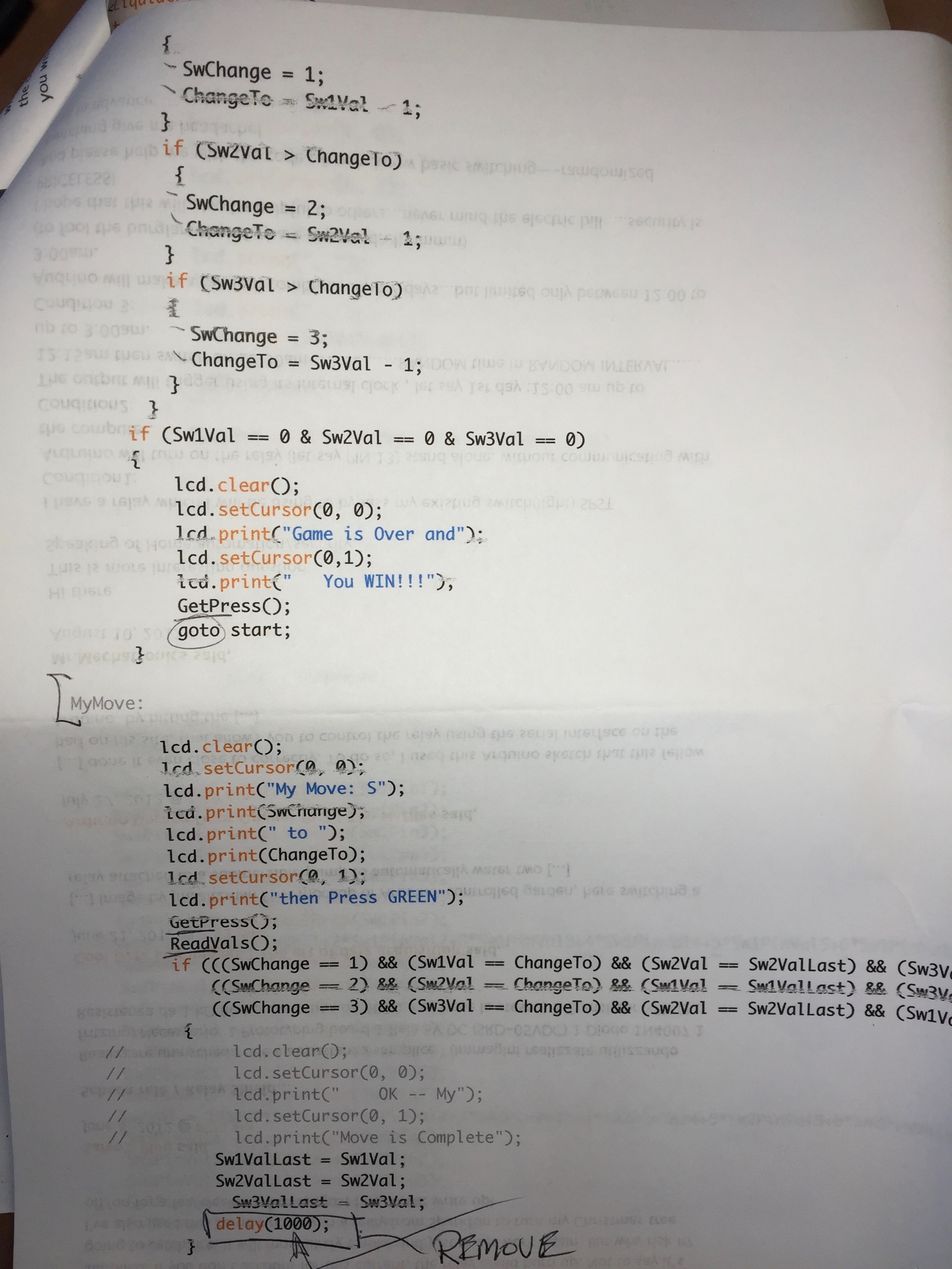
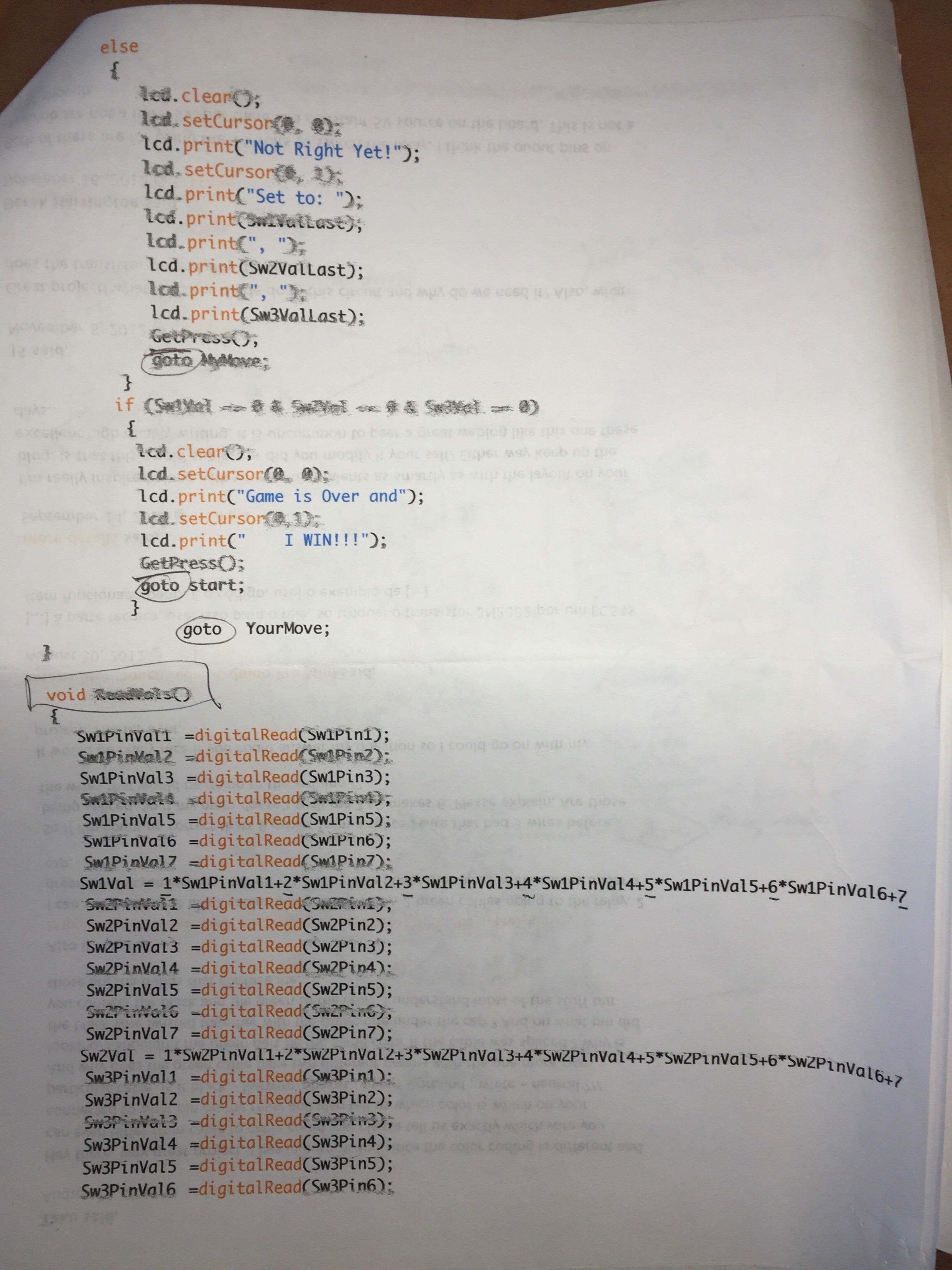
NimCode1

NimCode2

NimCode3

NimCode4

NimCode5

NimCode6

NimCode7

Cigar Box Antics

Leave a comment

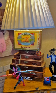
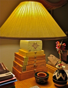
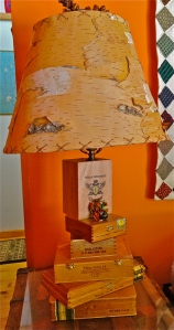
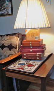
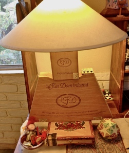
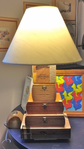
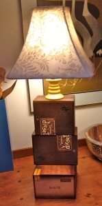
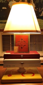
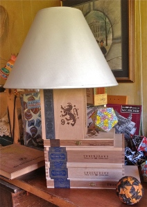
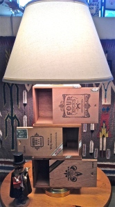
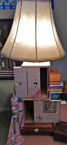
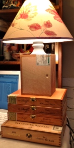
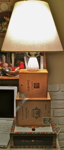
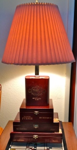
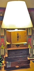
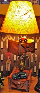
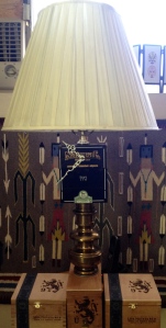
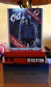
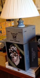
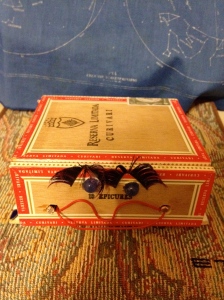
I recently came across a large stash of used Cigar Boxes, many more than I had stuff to store.  So I’ve been exploring ways to use these beautiful pieces of art …

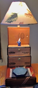
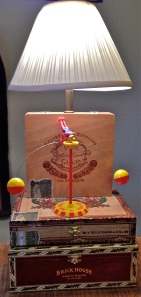
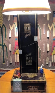
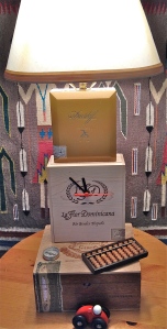
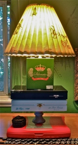
Here are my desk lamp creations:

Lamp1

Lamp2

Lamp3

Lamp4

Lamp5

Lamp6

Lamp7

Lamp8

Lamp9

Lamp15

Lamp10

Lamp11

Lamp12

Lamp13

Lamp14

Lamp16

Lamp17

Lamp18

Lamp19

Lamp20

Lamp21

Lamp21

Lamp23

Lamp24

Lamp25

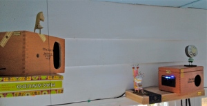
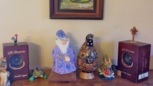
And speakers for my computers …

Speakers1

Speakers2

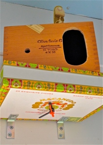
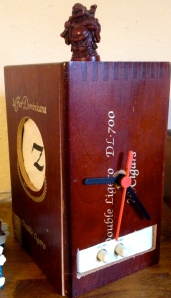
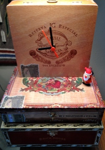
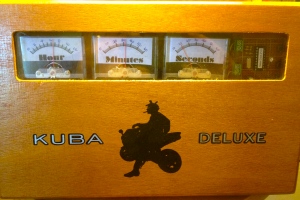
And clocks to keep me on time …

Clock

Clock2

Clock3

Clock4

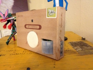
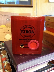
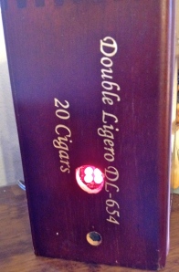
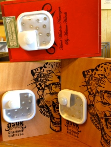
And Sensors to keep me safe … For most of them, they detect motion and turn on a light, chime, siren or my recorded voice.  One gives light emphasis to sounds.  And one sends me an e-mail video when it detects a sound or motion …

Sensor1

Sensor2

Sensor3

Sensor4

Sensor5

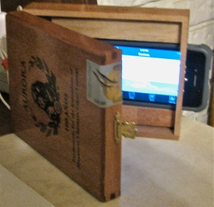
This is the coolest sensor of them all … it uses my iPhone and a free Apple App called Presence.  It secretly uses either camera and the microphone to report goings-on to my iPad which could be thousands of miles away.  There is much more that it does – if you’re interested, check the App out at the Apple store.  It uses old iPhones with working cameras and wi-fi and it can support a large number of them.  So, if you have an old iPhones that you are not using, I have a use for it!

Sensor6

Sensor1.1

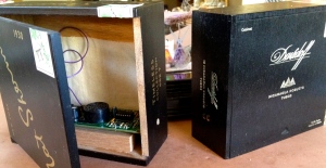
And now … they house Robots.  The first is a Lady of the Night, who Seeks the Light.

LightSeeker

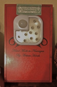
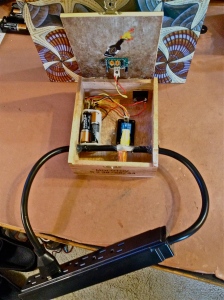
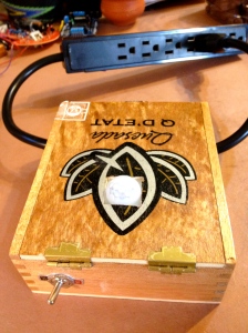
Now they help conserve energy by having AC feed itself.  Not really … It is an AC control box that uses an Infrared sensor (PIR) to detect humans and then turns on the AC for them.

ACcontrolW:PIC

ACcontrolW:PIC2


W.C. Fields used cigar boxes in his juggling routine …

I still have a lot remaining, and can get even more; so if you have an idea let me know.

This New House

Leave a comment

On the 23rd of September Garnet Lake was treated to a great show. The new home of Sue & Roy Keats was Raised. It is a modular home delivered on 2 large trucks. A major crane was moved into their driveway and the 2 halves were positioned and then unfolded. The entire operation was completed in about 3 hours. The companies involved were “Northgate Modular Homes” of Amsterdam NY and “Future Homes” of Port Jervis NY. Roy took the documenting movie which can be viewed below …